COLUMN (C-7):-
Assume column size = 10″ x 15″ = 150 sq. inch
a) Load Calculation:-
Load from F. B – A2,A3 = = 15.19 kip
Load from F. B – A3,A4 = = 8.25 kip
Load from F. B – A3,D3 = = 15.95 kip
Self weight of Column = x 150 x (10 – ) = 1.40 k
Factored load = 1.2 x 1.40 + 15.19 + 8.25 + 15.95
= 41.07 kip
Total column load for 6 – stored = 6 x 41.07 = 246.42 kip
b) Check for size:-
Pu = 243.11 (kip) (story -1) / ρg = 0.02
Pu = Ag [ .85f′c (1- ρg) + ρgfy]
Or, 246.42 = 0.80 x 0.65 x Ag [0.85 x 3 (1- 0.02) + .02 x 40]
Ag = 143.64 inch
Size of column = 10″ x 15″
Provided size = 150 in
c) Calculation of steel:-
Pu = [0.85 x f′c (Ag – Ast) + Ast fy]
Or, 150 = .80 x .65 x [.85 x 3 x (150- Ast) + Ast x 40]
Ast = 2.27 in
Use # 7 bars, Ap = 2.40 in
Tie bar:-
Use # 3 bar @ as Tie
S = 16 x Main bar dia = 16 x = 14″ c / c
S = 48 x Tie bar dia = 48 x = 18″ c / c
S = Minimum width of column = 10″ c /c
We use # 3 bar @ 10″ c / c
COLUMN (C-8):-
Assume column size = 10″ x 24″
a) Load Calculation:-
Load from F. B – B2,B3 = = 24.08 kip
Load from F. B – B3,B4 = = 13.08 kip
Load from F. B – B3,C3 = = 8.11 kip
Load from F. B – D3,B3 = = 3.12 kip
Self weight of Column = x 150 x (10 – ) = 2.25 k
Factored load = 24.08 + 13.08 + 8.11 + 1.2 x 2.25+20 k
= 67.97 kip
Total column load for 6 – story = 67.97 x 6 = 407.82 kip
b) Check for size:-
Pu = 407.82 (kip)
Pu = Ag [ .85f’c (1- ρg) + ρgfy]
Or, 407.82 = 0.80 x 0.65 x Ag [0.85 x 3 (1- .02) + .02 x 40]
Ag = 237.80 in
Size of column = 10″ x 24″
Provided size = 240 in
So, Ok
c) Calculation of steel:-
Pu = [0.85 f′c (Ag – Ast) + Ast fy]
Or, 407.82 = .80 x .65 x [.85 x 3 x (240- Ast) + Ast x 40]
Ast = 4.59 in
Use 8 # 7 bars st, Ap = 4.80 in
Tie bar:
Use # 3 bar as Tie
S = 16 x = 10″ c / c
S = 48 x = 18″ c / c
S = Minimum width of column = 10″ c / c
We use # 3 bar @ 10″ c / c
COLUMN (C-9):-
Assume column size = 10″ x 15″ = 150 sq. inch
a) Load Calculation:
Load from F. B – B3, C3 = = 7.81 kip
Load from F. B – C2, C3 = = 6.81 kip
Load from F. B – C3, C4 = = 3.06 kip
Load from stair Beam = = 19.38 kip
Self weight of Column = x 150 x (10 – )/1000 = 1.97 k
Factored load = 1.2 x 1.97 + 7.81 + 3.06 + 19.38 +20
= 59.42 kip
Total column load for 6. story = 6 x 59.42= 356.54 kip
b) Check for size:-
Pu = 116.232 kip
Pu = Ag [ .85f′c (1- ρg) + ρgfy]
Or, 356.54 = 0.80 x .65 x Ag [0.85 x 3 (1- .02) + .02 x 40]
Ag = 207.83 in
Size of column = 10″ x 21″
Provide, Ag = 10″ x 21″= 210 in
So, ok.
c) Calculation of steel:-
Pu = [0.85 f′c (Ag – Ast) + Ast fy]
Or, 356.54 = .80 x .65 x [.85 x 3 x (210- Ast) + Ast x 40]
Ast = 4.00 in
Use 10 # 6 bar straight.
Tie bar:-
Use # 3 bar as Tie
S = 16 x = 12″ c / c
S = 48 x = 18″ c / c
S = Minimum width of column = 10″ c / c
We use # 3 bar @ 10″ c / c
Check for lateral tie:-
S = = 4.75″ < 6″
So, Ok
No latered ties are required.
COLUMN (C-10):-
Assume column size = 10″ x 15″ = 150 sq. inch
a) Load Calculation:-
Load from F. B – A3, D3 = = 15.95 kip
Load from F. B – D3, D4 = = 9.29 kip
Load from F. B – D3, B3 = = 13.08 kip
Self weight of Column = 150 x x 9′ = 1.41 k
Factored load = 15.95 + 9.29 + 13.08 + 1.41 x1.2
= 40.00 kip
Total column load for 6- story = 6 x 40 = 240 kip
b) Check for size:-
Pu = 240 kip (Story -1)
Pu = Ag [ .85 x f′c (1- ρg) + ρg fy]
Or, 240 = .80 x .65 x Ag [.85 x 3 (1- 0.02) + .02 x 40]
Ag = 139.90 in
Size of column = 10″ x 14″
Provided size = 10″ x 15″= 150 Sq. inch.
Ok.
c) Calculation of steel:-
Pu = [0.85 f′c (Ag – Ast) + Ast fy]
Or, 240 = .80 x 0.65 [.85 x 3 (150- Ast) + Ast x 40]
Ast = 2.11 in
Use 4 # 7 bar st, Ap = 2.40in
Tie bar:
Use # 3 bar as Tie
S = 16 x = 14″ c / c
S = 48 x = 18″ c / c
S = Minimum width of column = 10″ c / c
We use # 3 bar @ 10″ c / c
Table:- 4.4. Details of sectional dimensions and reinforcement arrangement of all Columns (C – 1 ~ C – 10):
| Columngroup | Numberof Column | ColumnSize | Columnload | Area of steel req. (sq.inch) | QuantityOf bars | Tie barsspacing |
| Pu (kip) | Ast | Main bars | Use # 3 bars | |||
C – 1 | 02 | 10″ X 30″ | 516.34 | 6.10 | 14 # 6 | 10″ C/c |
C – 2 | 02 | 10″ X 18″ | 308.96 | 3.60 | 8 # 6 | 10″ C/c |
C – 3 | 02 | 10″ X 18″ | 289.77 | 2.52 | 6 # 6 | 10″ C/c |
C – 4 | 02 | 10″ X 20″ | 342 | 3.95 | 10 # 6 | 10″ C/c |
C – 5 | 02 | 10″ X 12″ | 189 | 1.53 | 6 # 5 | 10″ C/c |
C – 6 | 02 | 10″ X 12″ | 152.5 | 0.34 | 4 # 5 | 10″ C/c |
C – 7 | 02 | 10″ X 15″ | 246.42 | 2.27 | 4 # 7 | 10″ C/c |
C – 8 | 02 | 10″ X 24″ | 407.82 | 4.59 | 8 # 7 | 10″ C/c |
C – 9 | 02 | 10″ X 21″ | 356.54 | 4.00 | 10 # 6 | 10″ C/c |
C- 10 | 02 | 10″ X 15″ | 240.00 | 2.11 | 4 # 7 | 10″ C/c |
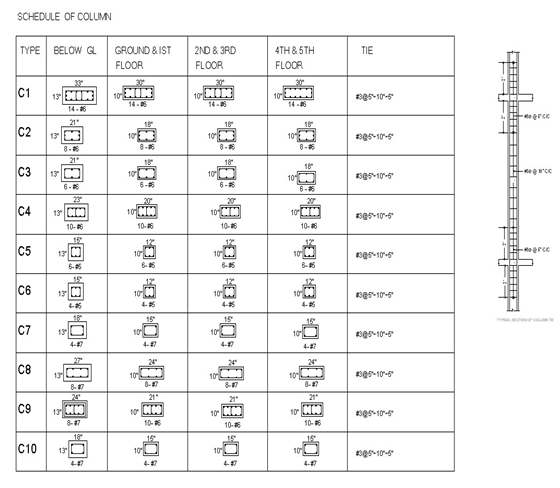
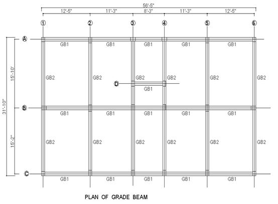
Figure Plan of Grade beam
Design of grade beams:
Design Data:–
Materials:-
Fy = 40 ksi
f′c = 3 ksi
wc = 150 pcf
w brick = 120 pcf
Thickness of wall on GB = 5″
Clear cover = 3″
Grade Beam GB-1:
Size = 10″ x 15″
Effective depth (d) = 15-3 = 12 inch
a) Load Calculation:-
Self weight of beam GB-1 = x 150 = 156.25 Ib/ft
All main wall weight = ( 10- )x120 = 430.00 Ib/ft
Total Dead load = 156.25 + 450 = 606.25 Ib/ft
Factored load GB-1 = 1.2 DL = 1.2 x 606.25
= 727.5 Ib/ft
= 0.73 k/ft
b) Moment Calculation and ‘d’ check:-
(-) Ve moment at Ext. support = = 7.04 k-ft
(+) Ve moment at Mid span = = 8.04 k-ft
(-) Ve moment at Int. support = = 11.26 k-ft
Mu = 11.26 k-ft
b = 0.85ß1 x x
= 0.85 x 0.85 x x
= 0.037
max = 0.75 b = 0.75 x 0.037 = 0.028
Mu = bd fy (1-0.59 x
Or 11.26 x 12 = 0.9 x 0.028×12 x d x 40 x (1-0.59 x .028 x
= 3.78″ < 12″
So, ok
c) Reinforcement Calculation:
Mid span steel:-
= = 62.03 < 200 psi
min = = = 0.005
min = = = 0.0041
As = bd = 0.005x 12 x 12 = 0.72 inch
Use 2 # 6 hanger bar.
Steel for Int. Support:-
= = 86.88 psi < 200 psi
min = 0.005
min = 0.0041
As = bd = 0.005x 12 x 12 = 0.72 inch
Use 2 # 6 hanger bar.
Steel for Ext. Support:-
= = 54.32 psi < 200 psi
As = bd = 0.005x 12 x 12 = 0.72 inch
Use 2 # 6 hanger bar.
d) Stirrup design:-
Vv = 1.15 x = 4.86 K
Vu = 4.86 – ( ) x.73 = 4.13 k
Vc = 2 bw d = 2 x 10 x 12 = 13.14 k
Shear strength of concrete,
Vc = .75 x 13.14 = 9.86 K
Since, Vc > Vd; no shear reinforcement is required.
Use # 3 bar @ = = 6″ c / c throughout beam length.
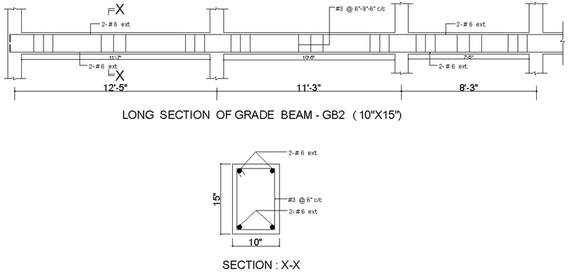
Grade Beam GB-2:
Size = 12″ x 15″
Effective depth, (d) = 15-3 = 12 inch
a) Load Calculation:-
Self weight of beam GB-2 = x 150 = 156.25 Ib/ft
All main wall weight = ( 10- ) x120 = 450.00 Ib/ft
Total Dead load = 156.25 + 450.00 = 606.25 Ib/ft
Factored load GB-2 = 1.2 DL = 1.2 x 606.25
= 727.5 Ib/ft
= 0.73 k/ft
b) Moment Calculation and d check:-
(-) Ve moment at Ext. support = = 11.43 k-ft
(+) Ve moment at Mid span = = 13.07k/ft
(-) Ve moment at Int. support = = 18.79 k-ft
Now, Mu = 18.79 k-ft
b = .85x 1 x x
= 0.85 x 0.85 x x
= 0.037
max = 0.75 x 0.037 = 0.028
Mu = bd fy (1-0.59 x
Or 18.79 x 12 = 0.9 x .028×12 x d x 40 x (1-0.59 x .028 x
= 4.88″ < 12″
So, ok
c) Reinforcement Calculation:
Mid span steel:-
= = 100.84 < 200 psi
min = = = 0.005
min = = = 0.0041
As = bd = .005x 12 x 12 = 0.72
Use 2 # 6 bar hanger
Steel for Int. Support:-
= = 144.98 psi < 200 psi
min = 0.005
As = 0.005x 12 x 12 = 0.72 inch
Use 2 # 6 bar hanger.
Steel for Ext. Support:-
= = 88.19 psi < 200 psi
min = 0.005
As = 0.005x 12 x 12 = 0.72 inch
Use 2 # 6 bar hanger .
d) Stirrup design:-
Vu = 1.15 x = 6.29 K
Vu = 6.29 – ( ) x .73 = 5.57 k
Vc = 2 bw d = 2 x 10 x 12 = 13.14 k
Shear strength of concrete,
Vc = 0.75 x 13.14 = 9.86 K
Since, Vc > Vd; no shear reinforcement is required.
Use # 3 bar @ = = 6″ c / c throughout beam length.
v\:* {behavior:url(#default#VML);}
o\:* {behavior:url(#default#VML);}
w\:* {behavior:url(#default#VML);}
.shape {behavior:url(#default#VML);}
Normal
0
false
false
false
EN-US
X-NONE
X-NONE
/* Style Definitions */
table.MsoNormalTable
{mso-style-name:”Table Normal”;
mso-tstyle-rowband-size:0;
mso-tstyle-colband-size:0;
mso-style-noshow:yes;
mso-style-priority:99;
mso-style-qformat:yes;
mso-style-parent:””;
mso-padding-alt:0in 5.4pt 0in 5.4pt;
mso-para-margin:0in;
mso-para-margin-bottom:.0001pt;
mso-pagination:widow-orphan;
font-size:10.0pt;
font-family:”Calibri”,”sans-serif”;}
table.MsoTableGrid
{mso-style-name:”Table Grid”;
mso-tstyle-rowband-size:0;
mso-tstyle-colband-size:0;
mso-style-priority:59;
mso-style-unhide:no;
border:solid windowtext 1.0pt;
mso-border-alt:solid windowtext .5pt;
mso-padding-alt:0in 5.4pt 0in 5.4pt;
mso-border-insideh:.5pt solid windowtext;
mso-border-insidev:.5pt solid windowtext;
mso-para-margin:0in;
mso-para-margin-bottom:.0001pt;
mso-pagination:widow-orphan;
font-size:10.0pt;
font-family:”Times New Roman”,”serif”;
mso-fareast-font-family:”Times New Roman”;}
Figure Reinfrocement Grade Beam ( GB-2 )
Table : Details of sectional dimensions and reinforcement arrangement of all grade beams ( GB- 1 GB – 2).
Grade Beam Group | Grade Beam Size | Moment (Kip-ft) | Area of steel req. (Sq. inch) | Quantity of bars | Stirrups (Spacing” C/c) | |||||
At Ext. M-Ve | At Mid M + Ve | At Int. M-Ve | At Ext. As-Ve | At mid As+Ve | At Int. M-Ve | Main bars | Extra Top/bottom | |||
GB – 1 | 10″ x 15″ | 7.04 | 8.04 | 11.26 | 0.72 | 0.72 | 0.72 | At Ext, Suppt: 2 # 6 | – | @ 6″ C/c |
At Mid, Span: 2 # 6 | – | @ 6″ C/c | ||||||||
At Int, Suppt: 2 # 6 | – | @ 6″ C/c | ||||||||
GB – 2 | 10″ x 15″ | 11.43 | 13.07 | 18.79 | 0.72 | 0.72 | 0.72 | At Ext, Suppt: 2 # 6 | – | @ 6″ C/c |
At Mid, Span: 2 # 6 | – | @ 6″ C/c | ||||||||
At Int, Suppt: 2 # 6 | – | @ 6″ C/c | ||||||||

Some are parts:
Analysis and Design of Building Components (Part 1)
Analysis and Design of Building Components (Part 2)
Analysis and Design of Building Components (Part 3)