ALAMOUTI Space Time Block Code for MIMO System
Introduction
In order that MIMO spatial multiplexing can be utilized, it is necessary to add coding to the different channels so that the receiver can detect the correct data.
There are various forms of terminology used including Space-Time Block Code – STBC, MIMO preceding MIMO coding, and Alamouti codes. Space-time block codes are used for MIMO systems to enable the transmission of multiple copies of a data stream across a number of antennas and to exploit the various received versions of the data to improve the reliability of data-transfer. Space-time coding combines all the copies of the received signal in an optimal way to extract as much information from each of them as possible. Space time block coding uses both spatial and temporal diversity and in this way enables significant gains to be made. Space-time coding involves the transmission of multiple copies of the data. This helps to compensate for the channel problems such as fading and thermal noise. Although there is redundancy in the data some copies may arrive less corrupted at the receiver.
When using space-time block coding, the data stream is encoded in blocks prior to transmission. These data blocks are then distributed among the multiple antennas (which are spaced apart to decor relate the transmission paths) and the data is also spaced across time.
A space time block code is usually represented by a matrix. Each row represents a time slot and each column represents one antenna’s transmissions over time.
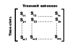
Within this matrix, Sij is the modulated symbol to be transmitted in time slot i from antenna j. There are to be T time slots and nT transmit antennas as well as nR receive antennas. This block is usually considered to be of ‘length’ T.
MIMO Alamouti coding
A particularly elegant scheme for MIMO coding was developed by Alamouti. The associated codes are often called MIMO Alamouti codes or just Alamouti codes. The MIMO Alamouti scheme is an ingenious transmit diversity scheme for two transmit antennas that does not require transmit channel knowledge. The MIMO Alamouti code is a simple space time block code that he developed in 1998.The Alamouti code is a so called Space-Time Block Code (STBC). A block code is a code that operates on a “block” of data at a time and the output only depends on the current input bits. There are other codes, such as “convolution codes” whose output is dependent on the current input, and also on the previous inputs. These codes may not necessarily produce the same output for a given input, depending on what the previous input bits were. The main reason for using a block code is that typically it requires much less processing power to decode a block code than a convolution code.
ALAMOUTI Space Time Block Code
In Space Time Block code output only depends on the current input bits. In convolution codes, the output only depends on the current input bits and on previous inputs. The convolution code may not produce the same output for a given input, because previous input is involved. The block code requires less power, to decode a block code, as compared to convolution code.
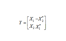
The Alamouti coding is described by the following matrix and Y is the encoder output, while X 1 and X2 are the input symbols. The “*” denotes the complex conjugate.
The figure is a block diagram of the transmitter module in MIMO system and using the Alamouti code. The binary bits enter a modulator and are converted to “symbols”. A symbol from modulator is represented by complex numbers. This symbol can be transmitted directly in a single antenna, Single Input Single Output (SISO), system. In MIMO system the complex symbols are fed into the Alamouti encoder. The Alamouti encoder maps the symbols onto the transmitter by using the above given matrix. In this matrix, rows represent the transmit antennas, and columns represent the time. The element of the matrix tells what symbol is to be transmitted from a particular antenna. The Alamouti code works with pairs of symbols at a time. It takes two time periods to transmit the two symbols.
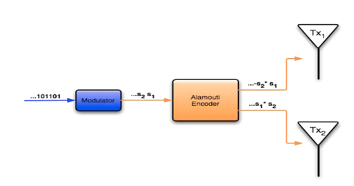
Figure : ALAMOUTI Space Time Block Code
Rayleigh Fading Channel
The Rayleigh fading model is particularly useful in scenarios where the signal may be considered to be scattered between the transmitter and receiver. In this form of scenario there is no single signal path that dominates and a statistical approach is required to the analysis of the overall nature of the radio communications channel.
Rayleigh fading is a model that can be used to describe the form of fading that occurs when multi path propagation exists. In any terrestrial environment a radio signal will travel via a number of different paths from the transmitter to the receiver. The most obvious path is the direct, or line of sight path.
However there will be very many objects around the direct path. These objects may serve to reflect, refract, etc the signal. As a result of this, there are many other paths by which the signal may reach the receiver.
When the signals reach the receiver, the overall signal is a combination of all the signals that have reached the receiver via the multitude of different paths that are available. These signals will all sum together, the phase of the signal being important. Dependent upon the way in which these signals sum together, the signal will vary in strength. If they were all in phase with each other, they would all add together. However this is not normally the case, as some will be in phase and others out of phase, depending upon the various path lengths, and therefore some will tend to add to the overall signal, whereas others will subtract.
Rayleigh fading model has support for troposphere and ionosphere signal propagation. It is most applicable when there is no distinct dominant path along LOS, between the transmitter and receiver. In this regard, Jakes introduced a model for Rayleigh fading based on summing sinusoids. Jakes model works equally, if the single path channel is being modeled or multi path frequency-selective channel is required. The Jakes model also popularized the Doppler spectrum associated with Rayleigh fading and as the result this Doppler spectrum is often termed as Jakes spectrum.
Rayleigh fading is a reasonable model when there are many objects in the environment that scatter the radio signal before it arrives at the receiver. The central limit theorem holds that, if there is sufficiently much scatter, the channel impulse response will be well-modeled as a Gaussian process irrespective of the distribution of the individual components. If there is no dominant component to the scatter, then such a process will have zero mean and phase evenly distributed between 0 and 2π radians. The envelope of the channel response will therefore be Rayleigh distributed.
Calling this random variable R, it will have a probability density function:
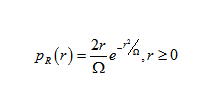
Where Ω = E(R2).
Often, the gain and phase elements of a channel’s distortion are conveniently represented as a complex number. In this case, Rayleigh fading is exhibited by the assumption that the real and imaginary parts of the response are modeled by independent and identically HYPERLINK “http://en.wikipedia.org/wiki/Independent_identically-distributed_random_variables”distributed zero-mean Gaussian processes so that the amplitude of the response is the sum of two such processes.
Alamouti STBC with two receive antenna
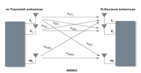
The principle of space time block coding with 2 transmit antenna and one receive antenna is explained in the post on Alamouti STBC. With two receive antenna’s the system can be modeled as shown in the figure below.
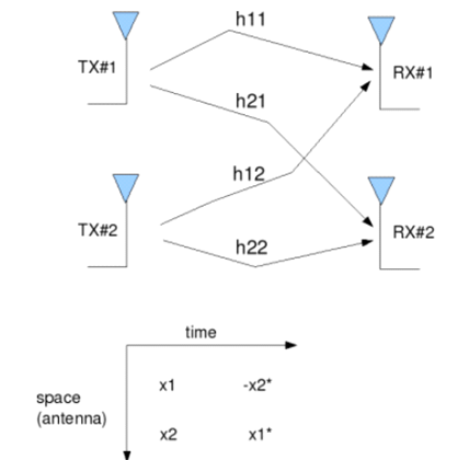
Figure : Transmit 2 Receive Alamouti STBC
The received signal in the first time slot is,Assuming that the channel remains constant for the second time slot, the received signal is in the second time slot is,
Where
- are the received information at time slot 1 on receive antenna 1, 2 respectively,
- are the received information at time slot 2 on receive antenna 1, 2 respectively,
- hij is the channel from ith receive antenna to jth transmit antenna,
- x1, x2 are the transmitted symbols,
- are the noise at time slot 1 on receive antenna 1, 2 respectively and
- are the noise at time slot 2 on receive antenna 1, 2 respectively.
Combining the equations at time slot 1 and 2,
Let, define H=
To solve for, need to find the inverse of H.
The term,
Simulation Model
Generating random binary sequence of +1’s and -1’s.Group them into pair of two symbols. Code it per the Alamouti Space Time code. Multiply the symbols with the channel and then add white Gaussian noise. Equalize the received symbols Perform hard decision decoding and count the bit errors Repeat for multiple values of Eb/No and plot the simulation and theoretical results.
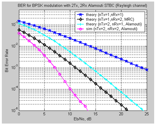
Figure: BER for BPSK modulation with 2Tx, 2Rx Alamouti STBC(RayleighChannel)
Observation
In Alamouti Space Time Block Coding with 2 transmitters and 1 receiver has around 3dB poorer performance. In Figure 3.3 the theoretical Alamouti calculation SNR is 24 db (approx.) and in the simulation SNR decreases 11 db (approx.). BER plot for nTx=1, nRx=2 Maximal ratio combining, the Alamouti Space Time Block Coding has around 5dB better performance.
Summary
BER performance is much better than 1 transmits 2 receive MRC case.In 1 transmitter and 2 receivers. The effective channel concatenating the information from 2 receive antennas over two symbols results in a diversity order of 4.In general, with m receive antennas, the diversity order for 2m transmit antenna Alamouti STBC.