Main focus of this report is to observe Implementation of Programmable Logic Controller (PLC) Circuits Using Digital Logic Design (DLD) Concept. Other objectives are to know about PLC and Functional description of PLC. Here also discuss how to PLC controller works and how to connection PLC to computer. Finally discuss the application of the PLC system and the Advantage of PLC.
Introduction
Industry has begun to recognize the need for quality improvement and increase in productivity after second world war. Flexibility have also became a major concern (ability to change a process have quickly became very important in order to satisfy consumer needs).There was always a huge electrical board for system controls, and not infrequently it covered an entire wall! Within this board there was a great number of interconnected electromechanical relays to make the whole system work. By word “connected” it was understood that electrician had to connect all relays manually using wires! An engineer would design logic for a system, and electricians would receive a schematic outline of logic that they had to implement with relays. These relay schemas often contained hundreds of relays. The plan that electrician was given was called “ladder schematic”. Ladder displayed all switches, sensors, motors, valves, relays, etc. found in the system. Electrician’s job was to connect them all together. One of the problems with this type of control was that it was based on mechanical relays. Mechanical instruments were usually the weakest connection in the system due to their moveable parts that could wear out. If one relay stopped working, electrician would have to examine an entire system (system would be out until a cause of the problem was found and corrected). The other problem with this type of control was in the system’s break period when a system had to be turned off, so connections could be made on the electrical board. If a firm decided to change the order of operations.
Literature Review
Programmable Logic Controllers (PLCs) have a history that dates back to the 1960s, yet there are still many in the automation industry who’ve had little experience with them. When it comes to learning about these products, or making the jump from other areas of automation to applications that involve PLCs, the transition can sometimes be difficult. It’s hard to know where to begin, and if you’ve been charged with the task of selecting one, it can be even harder to know which manufacturer or model to choose. To make the switch to PLCs, it’s important to have a basic understanding of what they are, what they do, and which PLC is right for your application. This thesis motivates definition and history of PLC. I have collected then reference books have Training of Program on Programmable Logic Controller (PLC),from Bangladesh Industrial Technical Assistant Centre (BITAC), Programmable Logic Controllers, Fifth Ed, W. Webb & Ronald A. Reis. Digital logic and computer Design, M. Morris Mano from then I know The functional description of PLC, I also collected from reference book . How PLC Controller Work and Structure of PLC system. The Programming a PLC controller and Kinds of PLC Software. I have also collected from web site from Google “Programmable Logic Controller”.
Motivation for this thesis
The era of hard automation has come to an end; the era of soft automation has already begun, and it is increasing day by day. So, Programmable logic Controller (PLC) design which is the core of soft automation seems an interesting and challenging topic to me. Its future and scope along with PLC development opportunity motivate me to explore some little parts of ongoing technology.
Statistical tools to be used
This is experimental and statistical tools will be used Siemens Logo soft Comfort, as MS-word, and MS-power point. And the used of equipment for project.
Aim of thesis
The programmable Logic Controller (PLC) is most important tool in the Industry sector and other electrical section. Because it is Flexible, Implementing Change & Correcting error, Newer Technology, Security, Documentation, Reliability & Maintainability, Ladder or Boolean programming method, Speed of Operation, Lower Cost, Visual Observation, Pilot Running, Ease of change by programming. The PLC are used to Industry sector and different electrical & electronics instruments controlling & protection. Such as Motor protection, Application of boiler, Water & Oil level indicator, Heater temperature control, Level flow indicator, Fault analysis, System protection, Boolean Algebra express, Latching process, Basic Logical Operation, Flickering lamp control, Proportional Integral Derivative (PID) Controller, etc.
Our objectives of this thesis are as follows:
- To study the what is PLC and Functional description of PLC.
- To study the how to PLC controller works and how to connection PLC to computer.
- To study the Kinds of PLC software.
- To study the programming language and data flow in PLC system.
- To study the LADDER diagram.
- To study the some example of PLC.
- To study the where are used of PLC.
- Discuss the elements of the Software LOGO! Soft Comfort.
- Discuss the application of the PLC system.
- Discuss the Advantage of PLC.
- Discuss the Some Example of PLC.
Organization of the thesis
This dissertation has the following structure. In section 2 we also discussed about the Programmable Logic Controller (PLC). In section 3 represents the Structure and working principal of PLC of PLC. Here we also talk about Input/ Output module, How PLC controller Connection out line of PLC, Structure of PLC and Data flow in PLC ,etc. In section 4, we are discussed the Programming of PLC, Classification of program and Ladder diagram, etc. Section 5 we also discussed about the Kinds of PLC software, The Software LOGO! soft control, Model of Logo, and we also discussed about the Application on PLC system, Advantage and Disadvantage of PLC system, and Populate of PLC, etc. Section 6 discussed about the Basic operations of Multiplexer, De-multiplexer, Encoder, Decoder Dateless, etc. Section 7 we also discussed the, Conclusion, Bibliography, Finally we summaries and concludes the dissertation and gives a brief outlook on possible future work.
Programmable Logic Controller
Programmable Logic Controllers (PLC) is essential controller equipment in modem Industrial control system. Though it is totally practical equipment, it can be changed by the program of its operation that’s why it is call Programmable Logic Controllers.
Control engineering has evolved over time. In the past humans was the main method for controlling system. More recently electricity has been used for control and early electrical control was based on relays. These relays allow power to be switched on and off without a mechanical switch. It is common to use relays to make simple logical control decisions. The development of low cost computer has brought the most recent revolution, the Programmable Logic Controller (PLC). The advent of the PLC began in the 1970s, and has become the most common choice for manufacturing controls. PLCs have been gaining popularity on the factory floor and will probably remain predominant for some time to come. Most of this is because of the advantages they offer.
- Cost effective for controlling complex systems.
- Flexible and can be reapplied to control other systems quickly and easily.
- Computational abilities allow more sophisticated control.
- Trouble shooting aids make programming easier and reduce downtime.
- Reliable components make these likely to operate for years before failure.
Characteristic of PLC
- Its Changeable operation.
- Processing element is used hear.
- Input & output signal Isolated as if PLC could not damage with electrical fault.
- Its reliabity is high
Functional Description of PLC
PLC is actually an industrial microcontroller system where you have hardware and software specially adapted to industrial environment. Special attention needs to be given to input and output, because in these blocks you find protection needed in isolating a CPU blocks from damaging influence that industrial environment can be bring to a CPU via input lines. Program unit is usually a computer used for writing a program (often in ladder diagram).
The control program can be entered into the PLC by using a simple from of high level language like ladder diagram, instruction code etc. The input device such as switch, push buttons, sensors and output device such as motors, relays, valves, lamps, etc are connected to PLC. The operator then enters a sequence of instructions (programs) into the memory of the PLC. The controller then monitors the inputs and outputs according to these programs and carries out the control rules for which it has been programmed.
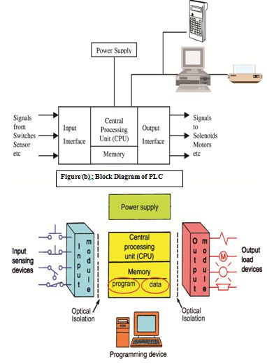
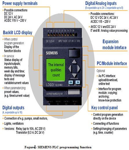
Figure(c) : Functional Description Of PLC
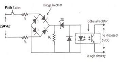
Power Supply
The electrical supply is used in bring electrical energy to central processing unit. Most PLC controllers work either at 24V DC or 220V AC. On some PLC controllers you’ll find electrical supply as a separate module. Those are usually bigger PLC controllers, while small and medium series already contain the supply module. User has to determine how much current to take from I/O module to ensure that electrical supply provides appropriate amount of current. Different types of module of modules use different amount of electrical current. This electrical supply is usually not used to start external inputs or outputs. User has to provide separate supplies in starting PLC controller inputs or outputs because than you can ensure so called “ pure “ supply for the PLC controller. With pure supply we mean supply where industrial environment can not affect it damagingly. Some of the smaller PLC controllers supply their inputs with voltage from a small supply source already incorporated into a PLC.
Memory
System memory (today mostly implemented in FLASH technology) is used by a PLC for an process control system. Aside from this operating system it also contains a user program translated from a ladder diagram to a binary form. FLASH memory contents can be changed only in case where user program is being changed. PLC controllers were used earlier instead of FLASH memory and have had EPROM memory instead of FLASH memory which had to be erased with UV lamp and programmed on programmers. With the use of FLASH technology this process was greatly shortened. Reprogramming a program memory is done through a serial cable in a program for application development.
User memory is divided into blocks having special functions. Some parts of a memory are used for storing input and output status. The real status of an input is stored either as “1” or as “0” in a specific memory bit. Each input or output has one corresponding bit in memory. Other parts of memory are used to store variable contents for variables used in user program. For example, timer value, or counter value would be stored in this part of the memory.
Read Only Memory (ROM)
ROM is a non-volatile memory that can be programmed only once. Its is therefore unsuitable. It is least popular as compared with other memory type.
Random Access Memory (RAM)
It stores user program and temporary buffer storage for the input /output buffer channel. The programs in the RAM can be changed by the user. However the prevent the loss of programs when the power supply is switched off., a battery is likely to be used in the PLC to maintain the RAM contents for a period of time. After a program has been developed in the ram it may be loaded into an EPROM memory chip and so made permanent.
Erasable Programmable Red only Memory(EPROM)
EPEROM holds data permanently just like ROM. It dose not require battery backup. However, Its content can be erased by exposing it to ultraviolet light. A prom writer is require to reprogram the memory.
Electrically Erasable Programmable Red only Memory(EPROM)
EEPROM combines the access flexibility of RAM and non-volatility of EPROM in one. Its contents can be erased and reprogrammed electrically, however, to a limit number of times.
Central Processing Unit (CPU)
The Central Processing Unit (CPU) is the brain of a PLC controller. CPU itself is usually one of the microcontrollers. It controls and processes all the operations with in the PLC. It is supplied with a frequency of typically between 1 and 8 MHz . This frequency determines the operating speed of PLC and provides the timing and synchronization for all elements in the system. A bus system carries information and data to and from the CPU.
Address bus
Address bus is used select a certain memory location of a device. When a particular address is selected by its address being placed on the address bus, only that location is open to communications from the CPU.
Data bus
Data bus is used to transport a word to or from the CPU and the memory or the input output interface. When address bus select a specific memory location then data of that location is available on data bus.
Control bus
Control bus is used to select the specific device i.e. ROM, RAM, I/O port etc. ROM, RAM, I/O port are selected by tri state method.
PLC controller inputs
Intelligence of an automated system depends largely on the ability of a PLC controller to read signals from different types of sensors and input devices. Keys, keyboards and by functional switches are a basis for man versus machine relationship. On the other hand, in order to detect a working piece, view a mechanism in motion, check pressure or fluid level you need specific automatic devices such as proximity sensors, marginal switches, photoelectric sensors, level sensors, etc. Thus, input signals can be logical (on/off) or analogue. Smaller PLC controllers usually have only digital input lines while larger also accept analogue inputs through special units attached to PLC controller. One of the most frequent analogue signals are a current signal of 4 to 20 mA and mV range voltage signal generated by various sensors. Sensors are usually used as inputs for PLCs. You can obtain sensors for different purposes. They can sense presence of some parts, measure temperature, pressure, or some other physical dimension, etc. (ex. inductive sensors can register metal objects). Other devices also can serve as inputs to PLC controller. Intelligent devices such as robots, video systems, etc. often are capable of sending signals to PLC controller input modules (robot, for instance, can send a signal to PLC controller input as information when it has finished moving an object from one place to the other.)
PLC Input Devices
- Push buttons
- Switches (limit switches, level switches, etc.)
- Sensors etc
PLC controller output
Automated system is incomplete if it is not connected with some output devices. Some of the most frequently used devices are motors, solenoids, relays, indicators, sound signalization and similar. By starting a motor, or a relay, PLC can manage or control a simple system such as system for sorting products all the way up to complex systems such as service system for positioning head of CNC machine. Output can be of analogue or digital type. Digital output signal works as a switch; it connects and disconnects line. Analogue output is used to generate the analogue signal (ex. motor whose speed is controlled by a voltage that corresponds to a desired speed).
PLC Output Devices
- Relay contacts
- Solenoid valves
- Signal devices (such as lamps, alarms, etc.)
- Motors Etc
Structure and working principal of PLC
Programmable controller
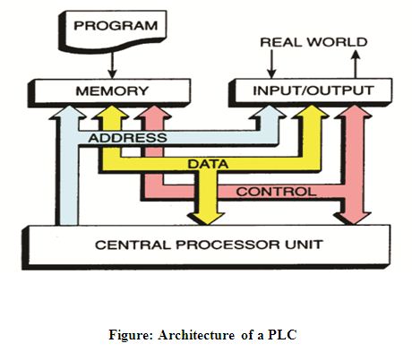
A PLC consists of a Central Processing Unit(CPU) containing an application program and Input and Output Interface modules, which is directly connected to the field I/O devices. The program control the PLC so that when an input signal from an input device turns ON, the appropriate response is made. The response normally involve turning On an output signal to some sort of output device.
How PLC controller works
A PLC works by continually scanning a program. We can think of this scan cycle as consisting of three steps. There are typically more than 3 but we can focus on the important parts and not worry about the other. Typically the others are checking the system and updating the current internal counter and timer values. Scanning process has three basic steps:
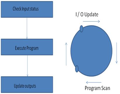
Figure : PLC Operation
Testing status
Step 1.
Testing input status. First, a PLC checks each of the inputs with intention to see which one of them has status ON or OFF. In other words, it checks whether a sensor , or a switch etc. connected with an input is activated or not. Information that processor thus obtains through this step is stored in memory in order to be used in the following step.
Step 2.
Program execution. Here a PLC executes a program, instruction by instruction. Based on a program and based on the status of that input as obtained in the preceding step, an appropriate action is taken. This reaction can be defined as activation of a certain output, or results can be put off and stored in memory to be retrieved later in the following step.
Step 3.
Checkup and correction of output status. Finally, a PLC checks up output status and adjusts it as needed. Change is performed based on the input status that had been read during the first step, and based on the results of program execution in step two. Following the execution of step 3 PLC returns to the beginning of this cycle and continually repeats these steps. Scanning time is defined by the time needed to perform these three steps, and sometimes it is an important program feature.
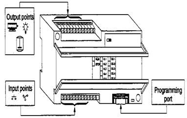
Connection out line of PLC
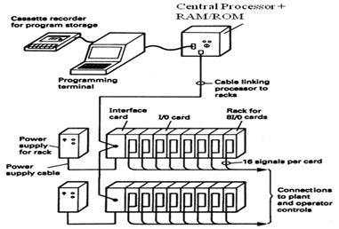
Figure(a) : Connection Outlet of PLC
PLC Input / Output Connection
Programming a PLC controller
PLC controller can be reprogrammed through a computer (usual way), but also through manual programs (consoles). This practically means that each PLC controller can programmed through a computer if you have the software needed for programming. Today’s transmission computers are ideal for reprogramming a PLC controller in factory itself. This is of great importance to industry. Once the system is corrected, it is also important to read the right program into a PLC again. It is also good to check from time to time whether program in a PLC has not changed. This helps to avoid hazardous situations in factory rooms (some automakers have established communication networks which regularly check programs in PLC controllers to ensure execution only of good programs).
Almost every program for programming a PLC controller possesses various useful options such as: forced switching on and off of the system inputs/outputs (I/O lines), program follow up in real time as well as documenting a diagram. This documenting is necessary to understand and define failures and malfunctions. Programmer can add remarks, names of input or output devices, and comments that can be useful when finding errors, or with system maintenance. Adding comments and remarks enables any technician (and not just a person who developed the system) to understand a ladder diagram right away. Comments and remarks can even quote precisely part numbers if replacements would be needed. This would speed up a repair of any problems that come up due to bad parts. The old way was such that a person who developed a system had protection on the program, so nobody aside from this person could understand how it was done. Correctly documented ladder diagram allows any technician to understand thoroughly how system functions.
Programming Language of PLC
PLC programming language refers to the method by which user communicates information to the PLC. There are three most common languages:
Ladder Diagram Language
The most common used by PLC language.
Boolean language
The statements refers to the basic AND, OR and NOT logic gate function.
Function chart system
It is a method of programming a control system that uses a more structured approach.
Classification of program
All functional elements need to execute a certain control process are called as a program. A program is stored in the RAM mounted on a CPU module or flash memory of an external memory module. The following table shows the classification of the program.
| Program type | Description |
| Scan program | The scan program is executed regularly in every scan, the CPU cannot execute not only the scan program but also other program. |
| The time driven interrupt program (TDI) | The TDI programs are executed with a constant time interval specified with the parameter setting. |
| Process driven interrupt program (PDI) | The PDI programs are executed only external interrupt input is applied and the corresponding interrupt routine is enable by EI instruction. |
| Subroutine program | The subroutine programs are executed when they are called by scan program with a CALL instruction. |
Processing Method
The following diagram shows that the CPU module process program when the CPU module is powered on or switch to run mode.
LADDER DIAGRAM
Ladder diagram can be understood by simplify considering an electrical circuit in figure:1. The diagram shows the circuit for switching on or off an electric motor. There is a dc voltage source heaving positive and negative terminal, a switch and motor. From the positive terminal current start to flow and finished it at negative terminal via the switch and the motor. Thus the circuit is completed. Now just redrawing the circuit using two vertical lines to represent the positive terminal (Left line) and negative terminal (Right line) of the source. Now the switch and motor are connect to a horizontal line in figure: Both circuit have the switch in series with the motor and supplied with electrical power when the switch is closed. The vertical lines are known as power rails and the horizontal component known as the rung. The shown in figure: are termed as ladder diagram.
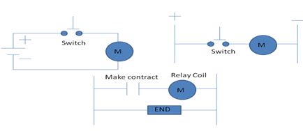
Figure : Comparison between ladder diagram and electrical diagram
Types of Software &Application of PLC
Kinds of PLC Software
We also discuss the software PLC. Some name of brand is given are below.
- Siemens Logo soft comfort
- LG
- Saia Burgess – PCD1
- Mitsubishi
The Software LOGO!Soft Comfort
Create ladder and function block diagrams simply by selecting, dragging and dropping the relevant functions and your connections. Make use of fully offline simulation of the entire switching program on the PC as well as online testing during operation.
Application of PLC system
- In Industry, there are many production tasks which are of highly repetitive nature. Although repetitive & monotonous, each stage needs careful attention of operator to ensure good quality of final product.
- Many times, a close supervision of processes cause high fatigue on operator resulting in loss of track of process control.
- Under all such conditions we can use PLCs effectively in totally eliminating the possibilities of human error.
ADVANTAGES OF PLC REDUCED SPACE
PLC are fully solid state & hence extremely compact as compared to hard – wired controller where in electro – mechanical devices are used.
- Easy to Program.
- The interfacing for inputs and outputs in inside the controller.
- Does not suffer from fatigue problem.
- Can be checked without field device.
- Can perform complex logic operation.
- Faster system response.
- Monitoring facilities available.
- High reliability.
- Easy to maintenance.
Disadvantage of PLC system
In this panel we can observer the following points
- There are too many wiring work in the panel.
- Modification can be quite difficult.
- Troubleshooting can be quite troublesome as you many require a skillful person.
- Power consumption can be quite high as the coil consumes power.
- Machine downtime is usually long when problems occur, as it takes a longer time to troubleshoot the control panel.
- Drawings are not updated over the years due to changes. Its causes longer downtime in maintenance and modification.
Populate of PLC
- Realiabity.
- Easy used friendly.
- Programming facilities.
- Process monitoring facilities.
Conclusion and Future work
Every Equipment is being conducted through Technology in the present modern world. At present every kinds of machine is being controlled automatically. PLC is one kinds of automatic controlled Instrument. In which machine, motor and various instrument are controlled. PLC is a modern invention of a technology.
We know This Thesis Programmable Logical Controller (PLC) we used to Industry sector and different electrical & electronics instruments controlling & protection. We prepare my dissertation paper helping from Bangladesh Industrial Technical Assistance Center (BITAC). Short Term Technical Training Programme on Programmable Logical Controller (PLC) and some book, web site and my dissertation teacher. Actually, we prepare my dissertation paper is study base. To draw the figure, we am using Computer soft program SIEMENCE logo Soft Comfort & Power point. As we can implement DLD (Digital Logic Design) design using PLC (Programmable Logic Controller) design efficiently and skillfully, it is better to explore and enhance the quality of PLC design instead of DLD design. we can implement PLC timers not only for the control of Industrial Process but also we can implement by using the PLC we control the alarm of drill replacement, conveyer control system, Flickering lamp, Motor protection, Heater temperature control, Level flow indicator, Fault analysis, System protection, Boolean Algebra express, Latching process, Basic Logical Operation, Multiplexer, De-multiplexer, Encoder, Decoder etc.
I am doing my thesis with new equipment of technology. I have tried a lot through my thesis the good conception of PLC and its uses. I will try to make same thing good through PLC in future which contribute in modern world and in the era of technology advancement. I will take a better concept with all types of instrument which is used in PLC. Furthermore I will try at my level How to use PLC in different instruments. I will make a Electronic Vote Counting in future in which vote counting can be done authentically and which will control through PLC. Through Electronic Voting Marching is used at present. But my machine will be ultra-modern one.