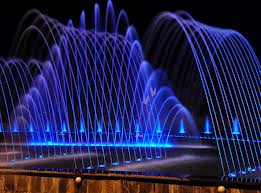
1.1 Introduction
A traditional water fountain is an arrangement where water issues from a source, fills a basin of some kind, and is drained away. A fountain is an arrangement where water is forced into the air under pressure creating jet. Water fountain may be of various kinds- fountains may be wall fountains or free-standing. The small water fountain made by us was a free standing type fountain. Different types of water fountains are splash fountain, Spray fountains, fountains for drinking water, animated fountain etc. In fountains sheets of water may flow over varied surfaces of stone, concrete or metal. Basins may overflow from one into another, or the overflow may imitate a natural cascade. Many fountains are located in small, artificial, ornamental ponds, basins and formal garden pools, and often they include sculpture.
One of the most common features of a fountain, if there is enough pressure, is one or more jets, in which water is forced into the air under pressure to some height. A famous example of such a modern fountain rises from the surface of Lake Geneva.
There is a need for good water quality in contemporary fountains, regardless of their avowed intended use. Regardless of the fact that some fountains are designed and built not as bathing fountains, but are rather used simply as architectural decor, people will often drink from, bathe or wash their hands in any fountain. Therefore minimum water quality standards are necessary, regardless of intended use.
The water fountain created by us was of three stages. It’s a variation among water fountains. The fountain was erected before fluid mechanics lab of BUET. A centrifugal pump was set inside the lab for supplying water.
1.2 Historical Background of water fountain
Early fountains depended on the natural gravitational flow of water, from a spring or aqueduct supplied by a distant and higher source of water, which provided hydraulic head .Hellenistic hydraulic engineers employed great originality in designing fountains, where the water pressure might be employed to animate automata and water organs.
Reciprocating motion was first described in 1206 by Iraqi engineer and inventor al-Jazari when the kings of the Artuqid dynasty in Turkey commissioned him to manufacture a machine to raise water for their palaces. The finest result was an machine called the double-acting reciprocating piston pump, which translated rotary motion to reciprocating motion via the crankshaft-connecting rod mechanism.
Other early fountains were geometrically regularized springs, developed in the classic Persian garden. These gardens were typically enclosed and were designed to provide relaxation. The effect of sunlight was the main concern regarding the structural aspect of the Persian garden design. Shapes and textures were specifically chosen for their ability to direct sunlight. In the 16th century elaborate fountain displays were garden features of Mannerist gardens of Central Italy and the Mughal gardens of India.
Early Modern English employed fountain to refer to a natural spring water or source, which the 16th century garden fountain might consciously imitate in a grotto.
1.3 Objective of the Project
Water fountain has various types of uses. It can be used for beautification of nature or aesthetic appeal. As a decorative addition to the window garden or merely a wall piece of modern art, the sound and sight of running water is very delightful. The cool touch of water against the fingertips reminds us about heavenly peace. The shape and size of garden water fountains is so varied and creative that the choice of any given fountain is as wide as the architect’s imagination. In water garden the fountain plays not only its traditional role as a centerpiece, but also that of an aerator if desired. In some traditions the water fountain is a source of spiritual enlightenment.
Water fountain can be installed for supplying drinking water. A water fountain or drinking fountain is designed to provide drinking water and has a basin arrangement with either continuously running water or a tap.
The objective of our project was to design a unique shape of staged water fountain that would add to the variety of choice for the people. Also its objective was to produce a cheap and economical water fountain for the indigenous customers. Although, some water fountains of continuous shape are available internationally, none of them has three stages.
1.4 How to choose and set up a Fountain
Fountains are cooling and soothing, and in arid climates, they lower the temperature of the surrounding air, which is a bonus for overheated plants and people. The trickle of a fountain also creates calming background music that can lessen the rumble of traffic and other undesirable noises. Easy-to-assemble kits make it possible to have a fountain in almost any size, from a half barrel to a column of water rising high above a pond.
Fountain types
A fountain can be a free-standing structure, a jet of spray shooting up from a pool or a wall-mounted spout that runs into a reservoir. In all cases, a pump is necessary to keep water circulating. At home stores and garden centers all the required equipment, including the fountain nozzle and power cords are available.
Style
For a formal garden, we may want a classic standing fountain. In a naturalistic garden, a small pool with a softly dancing water jet might be best. We can even find nozzles that spray water in various shapes, including tulip, daisy and mushroom forms.
kind of pump
A pump displaces fluid which creates flow. There are fixed displacement pumps and variable displacement pumps. Submersible pumps are made for safe, quiet operation underwater. Surface pumps sit above ground and must be concealed. We should choose a pump with a capacity slightly greater than the amount of water flow that the fountain requires.
Power safely
Plug an electric pump into a ground-fault circuit interrupter, which may need to be installed by a licensed electrician. The device will shut down power from the outlet to the pump when it senses any problems.
Fountain placement
We should make our freestanding fountain a centerpiece by situating it prominently at the intersection of two paths. A wall fountain is less conspicuous, and the element of surprise is part of its charm. Place it at the end of a walk or at the side of a patio or courtyard garden.
Simple and soothing
Small Japanese-style fountain should be installed in a quiet corner of the garden. A pump should be submerged in a stone bowl and a hidden tube may be used to connect it to a hollow bamboo pole. A second bamboo cane that will fill with water and tip to spill its contents should be placed gently into the basin. Adjustment of the pump to the bamboo emits a light trickle.
1.5 Scope of the project
The fountain in a water garden is an aesthetically pleasing addition to the already fantastic realm of imagination that these expressions of art produce. The fountain in a water garden not only enhances beauty. They also deliver in both the relaxing sounds of rushing water as well as serve to aerate and clean the water.
Water fountain can be used in front of any shopping malls, offices, community centers, houses and even hospitals to provide a soothing sight and explendid beauty. Water fountain can also be used as a bathing fountain intended for people to cool off in. Although many fountains were not designed as bathing fountains, children of all ages often use them for that purpose. Some fountains are fenced in, or have raised edges as a barricade to keep people out. In other situations, fountains are designed to allow easy access, and feature nonslip surfaces, so that people can safely use them to cool off in on hot summer days.
2.1Several rules
Its important to plan a water fountain properly. Here are some considerations which will be helpful for planning a water fountain.
Rule-1:
We should pick the right location. Before excavating for a pond or similar water feature we should check the location of utility lines. We should avoid placing a pond beneath the trees because it will fill with leaves and debris. If we are thinking about a spray fountain, it should be placed in a location protected from wind. Zoning code may govern how close to the property line we can install a water garden.
Rule-2:
Scale, proportion and style should be considered carefully. In most cases, a water feature should function as an accent-not a focal point. In a small garden, a decorative ceramic pot fitted with re-circulating bubbler may be used. A fountain with geometric lines will look best with a formal house and garden.
Rule-3:
We should decide whether the water is moving or still. Moving water can produce a pleasant murmur. On the other hand the tranquility of still water offers a glassy, calm surface that may be a beautiful reflecting pool in the garden. Moving water requires a power source to run the pump.
Rule-4:
We have to determine if the water feature will contain fish or plants. Fish will help the mosquito population down. Still water is generally the most favorable for the plants, moving water provides more oxygen for fish. If the pond is shallow water will evaporate quickly in direct sun. In this case, a float valve should be installed for controlling the water supply to maintain the proper water level.
2.2Types of water fountains on material basis
Fountains can be made from various types of material as required their life span. A variety of materials like cast iron , granite, slate, copper, concrete, resin etc can be used effectively for constructing a water fountain.
Aluminum water fountains:
These aluminum garden fountains are hand made in the USA of finest quality materials and measured against the highest standards of craftsmanship. Aluminum gives a traditional, early American look to these fountains.
Cast stone water fountains:
These beautiful fountains come in a wide range of styles including European, Landscape, Animals, Pacifica and statuary. These all are made with great care in the USA. Made of durable cast stone, each one is a work of art that will last so long, they will become family heirlooms.
Copper water fountains:
These copper water fountains are made specifically for use outdoors and have been carefully crafted of high quality materials. There are varieties of copper garden fountains such as wall hanging, free-standing sculptural and copper sprinkler sculptures that gently bathe our lawn and flower beds with glimmering streams of water.
Water fountains made of other materials
The versatility of outdoor fountains is unparalleled. Economical and durable, the quality materials used to make these water fountains are lightweight and strong so that they will withstand the elements and can be easily moved. In our small project we have used PVC pipes, wood to make a water fountain.
2.3 The basic steps of building a water fountain:
All that is needed to build a simple water fountain:
- A small water pump (less than 100 gallons per hour) and clear plastic tubing (1/2″ inner dimension or 5/8″ outer dimension).
- A container for supplying water.
- Rocks; pebbles; slate; crystals; semi-precious stones; drift wood pieces; shells. Anything that’ll take water, you can use in a fountain.
- Plants such as ivy, flowers, bamboo.
- Figurines.
Pump. Place the water pump in the bottom of the container, making sure the cord is draped toward the back. Be sure the electric wire is not bent too sharply. The pump can be in any spot. Use the suction cups that come with most pumps to stick it to the bottom of the container.
Once the pump is in place, put some water into the container and make sure the pump is working. Add tap water to more than cover the intake valve (2″ minimum). Plug the pump into the electrical outlet. If you are using a pump with a regulator, you may want to see what the different settings will do. Unplug the pump and adjust the water flow, if needed. You can also test out the pump and regulator in the sink or bucket prior to placing it in the container.
Tubing. The most common tubing size is 1/2″ inner diameter, 5/8″ outer diameter. Cut the tubing length to fit your container and design. Fit the clear plastic tubing on the pump spout and get about 8″ of the tubing to elevate the water.
Rocks. Use larger rocks and stones for filling the bottom (generally they won’t be seen) and smaller ones for accenting the visible top. Arrange the rocks and stones to anchor the water pump and to give the water flow a diverse, irregular path. Fill the container to about an inch from the top of the container with rocks and stones.
While covering the pump with rocks is not really necessary, it does make it easier to conserve room in a small container and helps muffle any humming noise. You may also choose to place larger rocks in the container around the pump first and then fill with other small rocks.
Accents. Add shells, crystals, or figurines to your water fountain. Accent your water fountain with ivy (either artificial or real), bamboo, flowers, or just leave it plain. Add moss and foliage as desired.
Adjustments. Plug in the pump and adjust the water volume and stones as needed. Suction excess water from the container with a turkey baster.
2.4 Water Fountain Pumps
We can have quiet, submersible, centrifugal fountain pumps in a variety of sizes and strengths for a water fountain. When choosing a pump it’s a good idea to consider the following-
- Whether the pump to be used for a fountain, watercourse or filter.
- What flow rate of the fountain should be.
- Volume of the reservoir pool (The flow rate should not exceed the pool’s volume.)
- What is the “head” i.e. the height of the highest point of the water is to be pumped over the water surface of the reservoir pool.
- The horsepower of the pump.
Different types of pumps used in water fountains:
There are a wide variety of pumps which can be used
2.5 Planning a WaterGarden using fountain
Until recently, water gardens were beyond the reach of many gardeners. Concrete — expensive and difficult to install — was the main material used in construction. Concrete also required special care to use and maintain. Most people had little choice but to call professionals for planning and installation, adding to the expense. A water garden was something one dreamed of but did not actually own.
With more modern pool lining materials — PVC and fiberglass are currently the main ones — material costs have dropped enormously and installation is easily carried out by anyone. We don’t even have to know how to nail two boards together to be able to install a water garden.
The amount of space available is also a factor. Even the tiniest yards have room for a small water garden (people have been known to raise goldfish and a single dwarf water lily in a tub on a balcony), but a truly balanced water garden with a variety of plants and animals takes a fair amount of space.
Pool depth is also a consideration. For a simple reflecting pool, we’ll need only a few inches of water, but very shallow pools are subject to extreme temperature change, which is not conducive to living organisms such as plants and fish. A minimum depth of 18 inches for much of the pond’s area is desirable. To overwinter plants and fish in cold climates, at least part of the pond should drop to three feet.
The shape of the pond will depend a great deal on the effect we wish to create. Square, rectangular, round, or oval ponds give a formal appearance to the yard, an effect heightened by using fountains. If we keep our yard neatly mowed, if shrubs and hedges are carefully trimmed, and other plantings are in formal beds, a geometric pond will suit it perfectly. If, on the other hand, our yard is composed of mixed borders and naturalistic plantings, a formal water garden would look out of place.
The topography of the site should also be considered. Fountain should not be placed in the lowest section of the yard: Any overflow could quickly turn the area into a bog. We have to make sure there is some possibility for drainage. If we plan to include a naturalistic cascade or waterfall, a yard with a somewhat abrupt slope is most fitting.
Design of water fountain
3.1Material
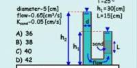
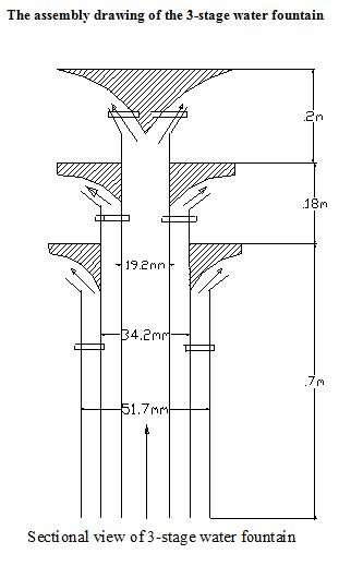
We have used PVC pipe of different diameters, wooden conical blocks .The nozzle of the fountain was also made of wood. Mild steel screws were used to fasten the pipes and to make pipes concencentric. Some screws were used to join the wooden nozzle with the PVC pipe. At three stages ,three nozzles of different shape were used . The bottom of the fountain(outer pipi) was connected to a reducer made of steel.
3.2Water supply
A centrifugal pump was used to deliver water through pipe. The pump was set inside the fluid machinery lab. A suction pipe was connected to the pump at its inlet port. At the other end of the pipe there was a foot valve. The pump was set to draw water from a reservoir. At the delivery port of the pump a flow control valve was connected. After the flow control valve a long hosepipe was connected and through it the water goes to the fountain.
3.3Pump
Two paralelly connected pumps were used for the project whose specifications are given below:
Toyo
Shallow Tube Well Pump
| Model TJ-10M | Power 0.5 HP |
| Voltage 220 V | Frequency 50 Hz |
| Suction lift- 5m | Max Head 7m |
| Single impeller | Made in China |
3.4Nozzle Design
Three diverging nozzles were designed for the fountain. The purpose of using nozzle is to spray out water at a desired shape which was like umbrella shape. The nozzles were designed and made by the pvc pipe and wood deflector. The design of three individual nozzle are described as below-
4.1Maintaining a Water Fountain
To Keep a water garden attractive and healthy is surprisingly easy. Steps to be taken for the maintenance of a water fountain-
- Plants should be removed occasionally to prune away dead or dying leaves. While we are at it, insert fertilizer tablets, about one per five quarts, into their containers.
- Any dead leaves and other organic material that has accumulated on the pool bottom should be removed.
- An occasional spray with a hose will knock any aphids that have developed on plant leaves into the water where fish will eat them.
- The filter should be cleaned occasionally according to the manufacturer’s instructions.
- Add water as necessary to maintain the proper water level.
- The water should not be murky as it loosens the charm of the fountain.
- Water can be changed occasionally as it emptied by siphoning. Larger pools can be easily emptied by attaching a piece of hose to the pump and allowing the water to drain away.
- The water level should be checked daily for the first week, adding fresh water as needed to keep the pump completely covered
- We can add a small amount of bleach to the water to cleanse the fountain. Periodically, clean the fountain, container, pump, rocks, etc. to remove any slime and algae.
4.2 Maintenance of Fountain pumps:
Fittings: The foot valve is used in the suction line of fountain pump to avoid dirt, mud etc. It also helps to priming. There was a flow control valve (gate valve) in the delivery
line. Hose pipe was connected to the delivery side by clips. All the fittings should be cleaned at times and the must be joined properly.
Cleaning the pump: Pump do need cleaning occasionally. It often depends where the water fountain is situated e.g. under trees with falling leaves. The manufacturer’s instructions should be followed with regard to cleaning.
Solar power: High quality solar powered fountain pumps are ideal where it is difficult to access electricity. They will work reasonably well in sun-shine. Adding extra solar panels can increase the power of the pump.
Electric power: Electric fountain pumps are powered either directly from the main or electricity is passed through a transformer to produce a low voltage current .A circuit breaker makes main electricity much safer to use in the garden.
5.1Calculation of flow rate
Different shape of fountain under different flow rate:
Table-5.1.1:Calculation of flow rate for fully opened valve-
| Observation no | Mass of empty bucket(kg) | Mass of water with bucket(kg) | Mass of water(kg) | Time (sec) | Mass flow rate(kg/s) | Average flow rate(kg/s) |
| 1 | 1.58 | 10.07 | 8.49 | 7.6 | 1.12 | |
| 2 | 1.58 | 10.7 | 9.12 | 8.1 | 1.126 | 1.174 |
| 3 | 1.58 | 13.245 | 11.665 | 9.5 | 1.23 | |
| 4 | 1.58 | 12.56 | 10.98 | 9.0 | 1.22 |
5.2 Pump capacity calculation:
Data for calculation:
Delivery side:
Inner diameter of 1st pipe : 19.2mm
Outer diameter of 1st pipe : 26.0mm
Length of first pipe : 1.08m
Inner diameter of 2nd pipe : 34.2mm
Outer diameter of 2nd pipe : 41.2mm
Length of 2nd pipe : 0.87m
Inner diameter of 3rd pipe : 51.7mm
Outer diameter of 3rd pipe : 60.0mm
Length of 3 rd pipe : 0.7m
Thickness of 1st pipe : 3.4mm
Thickness of 2nd pipe : 3.5mm
Thickness of 3rd pipe : 4.2mm
Distance between 1st & 2nd stage : 200mm
Distance between 2nd & 3rd stage : 180mm
Height of 3rd stage : 700mm
Length of hose pipe : 9.3metre
Diameter of hose pipe : 34mm
Length of short PVC pipe : 0.38m
Length of short steel pipe
connected to fountain : 0.15m
Length of steel pipe
connected to pump :1.22m
Minor loss co-efficient
Gate valve(Fully open) : 0.15
Suction side:
Length of suction pipe(PVC),Ls : 1.93m
Diameter of suction pipe,Ds : 0.026m
Length of short CI pipe : 0.254m
Minor loss co-efficient
Of check valve : 0.5
Calculation:
Mass flow rate, ۟m= 1.174 kg/s
Density of water, ρ= 997 kg/m3
Volume flow rate, Q=۟m/ρ
=1.174/997 m3/s
=1.18×10⁻³ m3/s
Cross sectional area of suction pipe,
As=πd2/4
=π×(.026)2/4
=5.31×10⁻⁴ m2
Velocity of water through suction pipe,
Vs = Q/As
=(1.18×10⁻³)/(5.31×10-4) m/s =2.22m/s
Viscosity of water at room temp, μ= 8.9×10⁻⁴ Nsm-2
Reynolds number, Re=ρdv/μ
=(997×0.026×2.22)/( 8.9×10⁻⁴)
=64659.37>4000
Hence, the flow is turbulent
Losses in suction side:
Using Reynolds number and relative roughness of pipe, we get from Moody diagram
f =0.013
Loss in PVC pipe, h1 =fLV2/2gD
= ( 0.013× 1.93×2.222)/(2×9.81× 0.026)
=0.2424m
Check valve & bend loss, h2= (k1+k2)v2/2g
= (0.5+0.5)×2.222/(2×9.81)
= 0.25m
Again from Moody diagram, for steel pipe
f=0.037
Loss in cast iron pipe, h3 = fLV2/2gD
= (0.037×0.25×2.22)/(2×9.81×0.026)
=0.877m
Total loss in suction side =0.2424m+0.25m+0.0877m
=0.58 m
Losses in delivery side:
Head loss in CI pipe, h1 = fLV2/2gD
= (0.037×1.22×2.22)/(2×9.81×0.026)
= 0.43m
Loss in T-joint & Gate valve, h2 = (k1+k2)V2/2g
= (2+0.15)×2.242/(2×9.81)
=0.55m
Hose pipe loss:
Cross sectional area of hose pipe A=πd2/4
=π×0.0342/4
=9.1×10⁻⁴ m2
Velocity through hose pipe = (1.18×10⁻³)/(9.1×10-4) m/s
=1.3 m/s
Reynolds number, Re = ρdv/μ
=(997×0.034×1.3)/ 8.9×10-4
=49513.93
Using Reynolds number & relative roughness of hose pipe, we get from Moody diagram, f=0.04
Now, Loss in hose pipe, h3 = fLV2/2gD
= (0.04×9.3×1.32)/(2×9.81×0.034)
= 0.9424m
Loss in short PVC pipe, h4 = fLV2/2gD
=( 0.013× 0.38×2.222)/(2×9.81× 0.026)
= 0.477m
Losses in fountain:
Flow rate through inner pipe(1st stage),
Q1 = (πdi2/4) ×v1
= (π×0.01922/4)×2.22 m3/s
=6.4×10⁻⁴ m3/s
Loss in 1st pipe(inner), h5= flv2/2gd
= ( 0.013× 1.08×2.222)/(2×9.81× 0.019) m
= 0.1822m
Flow rate through 2nd stage, Q2= (A2-A1)×v2
= (π/4)(0.03422-0.0262)×2.22
= 8.6×10⁻⁴ m3/s
Loss in 2nd stage pipe, h6= flv2/2g(d2-d1)
= (0.013×0.87×2.222)/(2×9.81× (0.0342-0.019)) m
= 0.1869m
Flow rate through 3rd stage, Q3= (A3-A2)×v3
= (π/4)(0.05172-0.0422)×2.22
=1.6×10⁻³ m3/s
Loss in 3rd stage pipe, h7= flv2/2g(d3-d2)
= (0.013×0.7×2.222)/(2×9.81× (0.0517-0.042)) m
=0.24 m
Total loss in delivery side = h1+h2+h3+h4+h5+h6+h7
= (0.43+0.55+0.9424+0.477+0.1822+0.1869+0.24) m
=2.9792m
Total head, H = Suction head+ Delivery head+ Losses+ Velocity head at exit
= (1.93+0.254)+(0.62+0.7+0.18+0.2)+(0.58+2.9792) + (2.222)/(2×9.81)×3
=8.22m
The output power, P0= γQH
=ρgQH
=997×9.81×1.18×10-3×8.22 watt
=96.5 watt
=0.13 hp
5.3 Variation of water flow with the annular gap of three stages
Table: Calculation of 1st stage flow when annular gap is 4mm
| No of obs | Mass of empty bucket(kg) | Mass of water with bucket(kg) | Mass of water(kg) | Time (sec) | Flow rate(kg/s) | Average flow rate(kg/s) |
| 1 | 1.58 | 6.2 | 4.62 | 11.2 | 0.42 | |
| 2 | 1.58 | 6.1 | 4.42 | 11.0 | 0.41 | 0.42 |
| 3 | 1.58 | 6.2 | 4.62 | 11.1 | 0.42 |
5.3.1 1st stage Nozzle:
| Annular gap(mm) | Discharge(kg/s) |
| 4.0 | 0.42 |
| 4.5 | 0.56 |
| 5.0 | 0.62 |
| 7.0 | 0.71 |
2nd stage Nozzle:
| Annular gap(mm) | Discharge(kg/s) |
| 3.0 | 0.523 |
| 3.5 | 0.63 |
| 4.0 | 0.72 |
| 4.5 | 0.8 |
3rd stage Nozzle
| Annular gap(mm) | Discharge(kg/s) |
| 3.0 | 0.577 |
| 3.5 | 0.67 |
| 4.0 | 0.725 |
| 4.5 | 0.83 |
6.1Discussion:
- In this project first of all three nozzles were designed for making a three stage continuous water fountain. The designed nozzle were made of wood, where other nozzles are built commercially using stainless steel. The nozzles were set to the fountain on trial basis. We have made three trials and finally selected the best fitted nozzles. Three concentric pipes were used for making the fountain. But the pipes could not be adjusted 100% concentrically this causes the flow of water to deform the desired cylindrical shape.
- The pipes could not be diverged in a uniform shape which causes some irregularities in the water flow. For better and continuous flow of water the pipe should be casted in a desired shape.
- There was a little problem in the shape of water of first stage nozzle. That happened due to the pins used to fasten the wood deflector with diverged pipe.
- The nozzles were made of wood. Hence the surface finished is not perfectly smooth which hinders the water flow.
- The divergence of 1st and 2nd stage nozzles should be designed more precisely for uniform flow.The 2nd & 3rd stage nozzle was adjusted by screws which interrupt the flow of water.
- The nozzle could not be adjusted with the PVC pipes concentrically with uniform clearance which causes the non-uniformity of shape.
- During the calculation of output power friction factor was determined from Moody diagram and using this factor pipe loss was determined from Darcy or Weisbach equation. The value of ‘f’ was an approximate value.
- Two pumps were connected parallely and using a T-joint flow was delivered. A gate valve was set at delivery to control the flow.There were some bends in the hose pipe that were not considered fully. That must cause determining the pump capacity somewhat smaller than the required value.
- At the upper stage of the fountain the shape of the jet was not so uniform. At the lower stage of nozzle the flow was of required shape.
- In the calculation of head losses the system’s nozzle loss were not considered instead the losses were assumed.
7.1Conclusion
This project is concerned of designing and constructing of a three stage continuous flow water fountain. During the execution of the project we have learnt a lot about the components and accessories of a water fountain such as supply pumps, piping system, flow control device, fountain nozzles, fountain materials etc. The constructed fountain is situated in front of the EME building of BUET. It can be installed anywhere to improve the scenic beauty. It is expected that the knowledge gained from this project will help us later in our professional life. We have learnt many practical things like how the materials can be collected, how various components should joined to one another etc while making the fountain. We wish to express our respect and gratitude to our supervisor to give us the opportunity of executing such a wonderful project.