Executive Summary
A roadmap for the development of new controls for power system stability is presented. The challenges are significant but the rewards in terms of economic payoff are high. The ability to push the limits of the power station depends on how well stable operation can be maintained against disturbances. The improvements in computers, communications and controllers are already being used in power station in many ways. By combining them to develop area-wide controls for power systems, stability can be controlled better to increase transmission limits. The roadmap outlined here ranks the conceptual developments by the difficulty of their implementation. The requirement of more complex computation or communication makes implementation more difficult, but several of the steps outlined above can be taken right now using existing technology without significant new development.
1. Introduction:
An Electric power station is a factory in which energy is converted from one form or another into Electrical Energy.
It is practically impossible to estimate the actual magnitude of the part that energy has played in the building up of present day civilization. The availability of energy has resulted higher agricultural and industrial production, better transportation facilities, a shorts but more beneficial working day and healthier and more balanced life.
1.1 Background
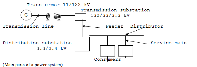
Step up transformer is used for step up the generation voltage to transmission voltage. At the transmission substation the voltage is stepped down to medium voltage. The feeders carry power to the distribution substations. At the distribution sub-station the voltage is to step down to low distribution voltage. Distributors are used to supply power to the consumers.
2. Body
2.1. Gas Turbine Power Station
Gas turbine power plant has relatively low cast and can be quickly put into commision.it requires less space. This plant is of smaller capacity and mainly used for peak load service. Gas turbine power plants are very promising for region where liquid or gaseous fuel is available in large quantities. Gas turbine installations require only a fraction of water used by their steam turbine counterparts. Gas turbine has made rapid progress during the past decade due mainly to the large amount of research. The size of gas turbine plants used in a large size used is about 50 MW. the thermal efficiency of gas turbine plant is about 22% to 25%.
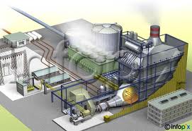
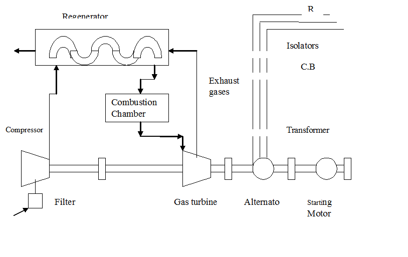
2.2. Schematic arrangement of Gas Turbine Power Station
The schematic arrangement (Fig. a) of a gas turbine power station can be divided into the following stages:
- Compressor
- Regenerator
- Combustion chamber
- Gas turbine
- Alternator
- Starting motor
- Electrical equipment
2.3 Classification of Gas Turbine Power Station
Gas turbine power plants may be classified according to the following criteria:
I. Types of load
II. Application
III. Cycle
IV. Number of shafts
V. Fuel
I. Types of Load. According to types of load the gas turbine power plants are classified as following.
a) Peak load plant. A gas turbine power plant is of smaller capacity may use for peak load service. Peaking power plants operate only during times of peak demand. Demand peaks around the middle of the afternoon, so a typical peaking power plant may start up a couple of hours before this point and shut down a couple of hours after. However, the duration of operation for peaking plants varies from a good portion of the waking day to only a couple dozen hours per year.
b) Base load plant. Gas turbine power plant is in a large size combined cycle plants may use as base load plants. Base load power plants operate continuously at maximum output. They only shut down to perform maintenance or if something break. They produce electricity at the lowest cost of any type of power plant. Base load power plants include coal, fuel oil, and nuclear, geothermal, hydroelectric, biomass and combined cycle natural gas plants.
c) Standby plant. Gas turbine power plants are being used as standby plants in combination with hydro-electric and steam power plants where the cost of gas is not excessive.
II.Application. A gas turbine power plant smaller in sizes and weight as compare to an equivalent steam or diesel power plant so that it is more suitable for consideration such as in ships, aircraft engines, locomotives and transports.
III.Cycle. The working of gas turbine power plant is mainly based on the two cycles:
a) Open cycle. In a simple open cycle plant fresh atmospheric air is drawn into by the compressor continuously and heat is added by combustion of fuel then the products are expanded through the turbine and exhausted to atmosphere.
b) Closed cycle. In the closed cycle plant air is continuously circulated and the heat by combustion of fuel is transferred to the air through heat transfer surface and thus the air does not mix with the products of combustion.
IV.Number of Shafts. According to number of shafts the open cycle gas turbine plant may be classified as follows:
a) Single shafts open cycle. In this arrangement air flows from low to high pressure compressor which delivers it to combustion chamber and gasses then expand in the turbine.
b) Twin shafts open cycle. The air enters the compressor and flows to combustion chamber then gases expand in the turbines.
V. Fuel. Various fuels used by gas turbine power plants are as follows:
a) Liquid fuel. This can be gasoline, kerosene and diesel oils.
b) Gaseous fuel. It can be natural gas, furnace gas, coal gas, blast furnace etc.
c) Solid fuel. It can be pulverized coal.
2.4. Characteristics of Gas Turbine Power Plants
Thermal efficiency of a gas turbine power plant varies with the effect of the temperature. With the addition of regeneration, inter-cooler and reheating the efficiency is raised. The approximate thermal efficiency for gas turbine stations on the assumption of atmospheric temperature of 15oC are as follows:
a. Up to 7.5 MW uncompounded plant without regeneration 15 to 20% and with regeneration 20 to 25%.
b. From 10 to 30 MW compound plant with regeneration 28 to 32%.
A 5oC change in inlet air temperature varies efficiency by about 3% and output by about 4% in open cycle plant.
2.5 Major parts of Gas Turbine Power Station
The main parts of gas turbine power plant are as following:
- Compressor
- Regenerator
- Combustion chamber
- Gas turbine
- Alternator
- Stating motor
g. Electrical equipments
- Compressor. The air at atmospheric pressure is drawn by the compressor via the filter which removes the dust from air. The rotator blades of compressor push the air between stationary blades to raise its pressure. Thus air at high pressure is available at output of the compressor. the various types of compressor used in gas turbine are as follows
1.Centrifugal compressor
2.Axial compressor
i.Centrifugal compressor. Centrifugal compressors use a vane rotating disk or impeller in a shaped housing to force the gas to the rim of the impeller, increasing the velocity of the gas. A diffuser (divergent duct) section converts the velocity energy to pressure energy. They are primarily used for continuous, stationary service in industries such as oil refineries, chemical and petrochemical plants and natural gas processing plants. Their application can be from 100 hp (75 kW) to thousands of horsepower. With multiple staging, they can achieve extremely high output pressures greater than 10,000 psi (69 MPa).
ii.Axial compressor. Axial-flow compressors use a series of fan-like rotating rotor blades to progressively compress the gas flow. Stationary stator vanes, located downstream of each rotor, redirect the flow onto the next set of rotor blades. The area of the gas passage diminishes through the compressor to maintain a roughly constant axial Mach number. Axial-flow compressors are normally used in high flow applications, such as medium to large gas turbine engines. They are almost always multi-staged. Beyond about 4:1 design pressure ratio, variable geometry is often used to improve operation.
- Regenerator. A regenerator is a device which recovers heat from the exhaust gases of the turbine. The exhaust is passed through the regenerator before wasting to atmosphere. The compressed air from the compressor passes through the tube of regenerator on its way to the combustion chamber. In this way compressed air is heated by hot exhaust gases.
- Combustion chamber. This high-pressure air then enters the combustion area, where a ring of fuel injectors injects a steady stream of fuel. The fuel is generally kerosene, jet fuel, propane or natural gas. If you think about how easy it is to blow a candle out, then you can see the design problem in the combustion area — entering this area is high-pressure air moving at hundreds of miles per hours.
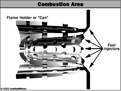
The injectors are at the right. Compressed air enters through the perforations. Exhaust gases exit at the left. You can see in the previous figure that a second set of cylinders wraps around the inside and the outside of this perforated can, guiding the compressed intake air into the perforations.
d. Gas turbine
At the left of the engine is the turbine section. In this figure there are two sets of turbines. The first set directly drives the compressor. The turbines, the shaft and the compressor all turns as a single unit.
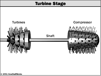
At the far left is a final turbine stage, shown here with a single set of vanes. It drives the output shaft. This final turbine stage and the output shaft are a completely stand-alone, freewheeling unit. They spin freely without any connection to the rest of the engine. And that is the amazing part about a gas turbine engine there is enough energy in the hot gases blowing through the blades of that final output turbine to generate 1,500 horsepower and drive a 63-ton M-1 Tank! A gas turbine engine really is that simple.
f. Alternator. The gas turbine is coupled to the alternator which converts mechanical energy of the turbine into electrical energy. The output from the alternator is given to the bus-bars through transformer, circuit breaker and isolators.
g. Starting motor. Before starting the turbine compressor has to start by an electric motor which is mounted on the same shaft as that of the turbine. The motor is energized by the batteries. Once the unit starts, a part of mechanical power of the turbine drives the compressor and there is no need of motor now.
h. Electrical equipments. The electrical equipments of a gas turbine power plant include alternators, transformers, circuit breaker and other switching and protective devices.
3. Method of voltage control
There are several methods of voltage control. In each method, the system voltage is changed in accordance with the load to obtain a fairly constant method of voltage control in an a.c power system:-
- by excitation control
- by using tap changing transformers
- auto-transformer tap changing
- booster transformers
- induction regulators
- by synchronous condenser
3.1. Excitation control: When the load on the system change, the terminal voltage of the alternator also varies due to the changed voltage drop in the synchronous reactance of the armature. The voltage of the alternator can be kept constant by changing the field current of the alternator in accordance with the load. This is known as excitation control method. The excitation of alternator can be controlled by the use of automatic or hand operated regulator acting on the field circuit of the alternator. The first method is preferred in method practice. There are two main types of automatic voltage regulator viz
- Terrill regulator
- Brown-Bovri regulator
3.1.1Tirril regulator:-In this type of regulator, a fixed resistance is cut in and cut out of the exciter field circuit of the alternator. This is achieved opening and closing a shunt circuit across the exciter rheostat for this reason, it is also known as vibrating type voltage regulator.
- Main contact: There are two levers at the top which carry the main contacts at the facing ends. The left hand lever is controlled by the exciter magnet whereas the right hand lever is controlled by an a.c. magnet known as main control magnet.
- Exciter magnet: This magnet is of the ordinary solenoid type and is connected across the exciter mains. Its exciting current is, therefore, proportional to the exciter voltage. The counter balancing force for the exciting magnet is provided by four coil spring.
- A.C. magnet: It is also of solenoid type and is energised from a.c. bus-bars. It carries series as well as shunt excitation. This magnet is so adjusted that with normal load and voltage at the alternator, the pulls of the two coils are equals and opposite, thus keeping the right-hand lever in the horizontal position.
- Differential relay: It essentially consists of a U-shaped relay magnet which operates the relay contacts. The relay magnet has two identical windings wound differentially on both the limbs. These windings are connected across the exciter mains-the left hand one permanently while the right hand one has its circuit completed only when the main contacts are closed. The relay contact are arranged to shunt the exciter-field rheostat R. A capacitor is provides across the relay contacts to reduce the sparking at the relay contacts are open.
- Operation: – the two control magnets are so adjusted that with normal load and voltage at the alternator, their pulls are equal, thus keeping the main contacts open. In this position of main contacts, the relay magnet remains energised and pulls down the armature carrying one relay contact. Consequently, relay contact remain open and the exciter field rheostat is the field circuit. When the load on the alternator increases, its terminal voltage tends to fall. This cause the series excitation to predominate and the a.c magnet pulls down the right-hand leaver to close the main contacts. Consequently, the relay magnet is de-energised and releases the armature carrying the relay contact. The relay contracts are closed and the rheostat R in the field circuit is short circuited. This increases the exciter-voltage and hence the excitation of the alternator. The increased excitation causes the alternator voltage to rise quickly. At the same time, the excitation of the exciter magnet is increased due to the increase in exciter voltage. Therefore, the left hand lever is pulled down, opening the main contracts, energising the relay magnet and putting the rheostat R again in the field circuit before the alternator voltage has time to increase too far. The reverse would happen should
3.1.2 BROWN-BOVERI REGULATOR
In this type of regulator, exciter field rheostat is varied continuously or in small steps instead of being first completely cut in and then completely cut out as in trill regulator. For this purpose, a regulating resistance is connected in series with the field circuit of the exciter. Fluctuations in the alternator voltage are detected by a control device which actuates a motor. The motor drives the regulating rheostat and cuts or cuts in some resistance from the rheostat, thus charging the exciter and hence the alternator voltage.
In the circuit of a brown-boveri voltage regulator. It also works on the” overshooting the mark principle “and has the following four important parts:
- Control system: the control system is built on the principle of induction motor. it consists of two windings A and B on an annular core of laminated sheet steel. The winding A is excited from two of the generator terminals through resistance U and U’ while a resistance R is inserted in the circuit of winding B.
- Mechanical control torque: the electric torque produced by the current in the split phase winding is opposed by a combination of two springs which produce a constant mechanical torque irrespective of the position of the drum. Under steady deflected state, mechanical torque is equal and opposite to the electric torque.
- Operating system: in consists of field rheostat with contact device. the rheostat consists of a pair of resistance elements connected to the stationary contact block Cb. these two resistance sectors R are connected in series with each other and then in series with the field circuit of exciter. On the inside surface of the contact blocks roll the contact sectors Cs when the terminal voltage of the alternator changes.
3.2. Induction regulator: An induction regulator is essentially a constant voltage transformer, one winding of which can moved w.r.t.the other, thereby obtaining a variable secondary voltage. The primary winding is connected across the supply while the secondary winding is connected in series with the line whose voltage is to be controlled.
Single-phase induction regulator: a single phase induction regulator is illustrated in fig. in construction, it is similar to a single phase induction motor except that the rotor is not allowed to rotate continuously but can be adjusted in any position either manually or by a small motor. The primary winding AB is wound on the stator and is connected across the supply line. The secondary winding CD is wound on the rotor and is connected in series with the line voltage is to be controlled.
Three phase induction regulator: in construction, a 3-phase induction regulator is similar to a 3-phase induction motor with wound rotor except that the rotor is not allowed to rotate continuously but can be held in any position by means of a worm gear. the primary winding either in star or delta are wound on the stator and are connected across the supply. The secondary windings are wound on the rotor and the six terminals are brought out since these windings are to be connected in series with the line whose voltages to be controlled.
3.3. Tap-changing transformers:
The excitation control method is satisfactory only for relatively short lines. however, it is not suitable for long lines as the voltage at the alternator terminals will have to be varied too much in order that voltage at the far end of the line may be constant. Under such situations, the problem of voltage control can be solved by employing other method. The voltage drop in the line is supplies by changing the secondary e.m.f of the transformer through the adjustment of its number of turns.
3.3.1. off load tap-changing transformer: at figure shows the arrangement where a number of tapping have been provide on the secondary. as the position of the tap is varied, the effective number of secondary turns is varied and hence the output voltage of the secondary can be changed. thus referring to fig when the movable arm makes contact with stud 1,the secondary voltage is minimum and when with stud 5,it is maximum. during the period of light load, the voltage across the primary is not much below the alternator voltage and the load increases, the voltage can be kept at the previous value by placing the movable arm on a higher stud.
3.3.2. on-load tap-changing transformer: in supply system, tap-changing has normally to be performed on load so that there is no interruption to supply. in fig shows diagrammatically one type of on-load of on-load tap-changing transformer. the secondary consists of two equal parallel windings which have similar tapping 1a…..5a and 1b…5b.in the normal working conditions, switches a,b and tapping with the same number remain closed and each secondary winding carries one-half of the total current. The secondary voltage will be maximum when switches a,b and 5a,5b are closed. However, the secondary voltage will be minimum when switches a,b and 1a,1b are closed.
3.4. Auto-transformer tap-changing
At fig shows diagrammatically auto-transformer tap changing. Here, a mid-tapping auto-transformer or reactor is used. one of the lines is connected to a series of switches across the odd tapings and the other end b is connected to switches across even toppings’ short circuiting switch s is connected across the auto transformer and remains in the closed position under normal operation. in the normal operation there is no inductive voltage drop across the auto-transformer. Referring to fig it is clear that with switch 5 closed, minimum secondary turns are in the circuit and hence the output voltage will be the lowest. On the other hand, the voltage will be maximum when switch 1 is closed.
3.5. Booster transformer
Sometimes it is desired to control the voltage of a transmission line at a point far away from the main transformer. this can be conveniently achieved by the use of a booster transformer as shown in fig. the secondary of the booster transformer is connected in series with the line whose voltage is to be controlled. the primary of this transformer is supplied from a regulating transformer with on-load tap-changing gear. the booster transformer is connected in such a way that its secondary injects a voltage in phase with the line voltage. the voltage at AA is maintained constant by tap-changing gear in the main transformer. However, there may be considerable voltage drop between AA and BB due to frailly long feeder and tapping of loads. the voltage at BB is controlled by the use of regulating transformer and booster transformer, by changing the tapping on the regulating transformer, the magnitude of the voltage injected into the line can be varied.
3.6. Voltage control by synchronous condenser
The voltage at the receiving end of a transmission line can be controlled by installing specially designed synchronous motors called synchronous condense at the receiving end of the line. The synchronous condenser supplies wattles leading KVA to the line depending upon the excitation of the motor.
1. without synchronous condenser.
2. With synchronous.
4. Economics
Gas turbine power plants are particularly useful and economical where liquid or gaseous fuel is available in large/ quantities and the cost of gas is not excessive. Cost of a gas turbine power plant can be divided as following.
- Capital cost. Overall initial cost of a gas turbine power plant is relatively low as compared to steam power plant of equal size.
- Fixed cost. A gas turbine power plant has lower fixed charges than that of a gas power plant of same size.
- Running cost. Natural gas is used in a gas turbine power plant which is very cheap and due to high reliability and flexibility in operation; control of a gas turbine plant is very simple and easy.
5. Priority
5.1. Advantages of gas turbine engines
- Very high power-to-weight ratio, compared to reciprocating engines (ie. most road vehicle engines);
- Smaller than most reciprocating engines of the same power rating;
- Moves in one direction only, with far less vibration than a reciprocating engine, so very reliable;
- Simpler design.
- Low operating pressures.
- High operation speeds.
- Low lubricating oil cost and consumption.
5.2. Disadvantages of gas turbine engines
- Cost is much greater than for a similar-sized reciprocating engine (very high-performance, strong, heat-resistant materials needed);
- Use more fuel when idling compared to reciprocating engines – not so good unless in continual operation.
6. Summary
A gas turbine extracts energy from a flow of hot gas produced by combustion of gas or fuel oil in a stream of compressed air. It has an upstream air compressor (radial or axial flow) mechanically coupled to a downstream turbine and a combustion chamber in between. “Gas turbine” may also refer to just the turbine element.Energy is released when compressed air is mixed with fuel and ignited in the combustor. The resulting gases are directed over the turbine’s blades, spinning the turbine, and mechanically powering the compressor. Finally, the gases are passed through a nozzle, generating additional thrust by accelerating the hot exhaust gases by expansion back to atmospheric pressure.Energy is extracted in the form of shaft power, compressed air and thrust, in any combination, and used to power aircraft, trains, ships, electrical generators, and even tanks.
In a gas turbine power plant the air is compressed by compressor and is led to the combustion chamber. In this chamber heat is added to the compressed air either by burning fuel in the chamber or by the use of air heaters and thus raising its temperature. The hot and high pressure air then passed to the gas turbine where it expands and converts to mechanical energy. The gas turbine drives the alternator which converts mechanical energy into electrical energy.
7. Recommendation
This gas turbine power plant station is simple and requires fewer auxiliaries and their control is easy. This power station size weighted as compared to an equivalent steam power plant. This power plant size and weighted are the main consideration such as ships, aircraft and locomotives, a gas turbine is more than that of a diesel engine plant. It’s initial and operating costs are much lower than that of equivalent steam power plant.