ENTITY RELATIONSHIP MODEL
Entity Relationship Model :
Entity Relationship Model ( E-R ) data model is based on a perception of a real world that consists of a set of basic objects called entities and of relationships among these objects. It was developed to facilitate database design by allowing the specification of an enterprise scheme, which represents the overall logical structure of a database.
Basic Concepts :
There are three basic notations that the E-R data model involves – entity sets, attributes and relationship sets.
Entity Relationship (ER) modeling
- is a design tool
- is a graphical representation of the database system
- provides a high-level conceptual data model
- supports the user’s perception of the data
- is DBMS and hardware independent
- had many variants
- is composed of entities, attributes, and relationships
Entity Sets :
- An entity is any object in the system that we want to model and store information about Individual objects are called entities
- Groups of the same type of objects are called entity types or entity sets
- Entities are represented by rectangles (either with round or square corners)
- There are two types of entities; weak and strong entity types.
- Sometimes it is useful to try out various examples of entities from an ER model. One reason for this is to confirm the correct cardinality and optionality of a relationship.
Attributes :
- All the data relating to an entity is held in its attributes.
- An attribute is a property of an entity.
- Each attribute can have any value from its domain.
- Each entity within an entity type:
- May have any number of attributes.
- Can have different attribute values than that in any other entity.
- Have the same number of attributes.
- Attributes can be- 1. simple or composite , 2. single-valued or multi-valued
- Attributes can be shown on ER models
- They appear inside ovals and are attached to their entity.
- Note that entity types can have a large number of attributes… If all are shown then the diagrams would be confusing. Only show an attribute if it adds information to the ER diagram, or clarifies a point.
Relationships :
- A relationship type is a meaningful association between entity types
- A relationship is an association of entities where the association includes one entity from each participating entity type.
- Relationship types are represented on the ER diagram by a series of lines.
- As always, there are many notations in use today…
- In the original Chen notation, the relationship is placed inside a diamond.
Problems with ER Models :
There are several problems that may arise when designing a conceptual data model. These are known as connection traps.
There are two main types of connection traps:
- fan traps
- chasm traps
Constructing an ER model :
Before beginning to draw the ER model, read the requirements specification carefully. Document any assumptions you need to make.
- Identify entities – list all potential entity types. These are the object of interest in the system. It is better to put too many entities in at this stage and them discard them later if necessary.
- Remove duplicate entities – Ensure that they really separate entity types or just two names for the same thing.
- Also do not include the system as an entity type
- e.g. if modeling a library, the entity types might be books, borrowers, etc.
- The library is the system, thus should not be an entity type.
- List the attributes of each entity (all properties to describe the entity which are relevant to the application).
- Ensure that the entity types are really needed.
- are any of them just attributes of another entity type?
- if so keep them as attributes and cross them off the entity list.
- Do not have attributes of one entity as attributes of another entity!
- Mark the primary keys.
- Which attributes uniquely identify instances of that entity type?
- This may not be possible for some weak entities.
- Define the relationships
- Examine each entity type to see its relationship to the others.
- Describe the cardinality and optionality of the relationships
- Examine the constraints between participating entities.
- Remove redundant relationships
- Examine the ER model for redundant relationships.
ER modeling is an iterative process, so draw several versions, refining each one until you are happy with it. Note that there is no one right answer to the problem, but some solutions are better than others!
Mapping Constraints :
An E-R scheme may define certain constraints to which the contents of a database must conform.
a) Mapping Cardinalities: Mapping Cardinalities express the number of entities to which another entity can be associated via a relationship. Different form of mapping cardinalities are –
One-to-One:
An entity in A is associated with at most one entity in B and an entity in B is associated with at most one entity in A.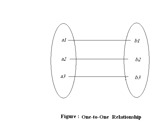
For example , A customer is associated with at most one account. An account is associated with at most one customer.
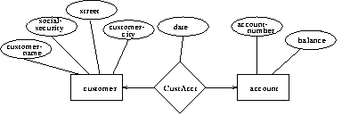
Figure : One-to-one from customer to account
One-to-Many:
An entity in A is associated with any number of entities in B and an entity in B, however, can be associated with at most one entity in A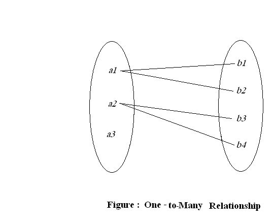
For example , in the one-to-many relationship an account is associated with at most one customer. A customer is associated with several accounts.
Many-to-one:
An entity in A is associated with at most one entity in B and an entity in B, however, can be associated with any number of entities in
For example , in the many-to-one relationship a customer is associated with several accounts , an account is associated with at most one customer.
Figure : Many-to-one from customer to account
Many-to-many:
An entity in A is associated with any number of entities in B and an entity in B is associated with any number of entities in A.
4.5 Keys :
- A key is a data item that allows us to uniquely identify individual occurrences or an entity type.
- A candidate key is an attribute or set of attributes that uniquely identifies individual occurrences or an entity type.
- An entity type may have one or more possible candidate keys, the one which is selected is known as the primary key.
- A composite key is a candidate key that consists of two or more attributes
- The name of each primary key attribute is underlined.
Several types of keys are –
Primary Key:
A primary key is a field or combination of fields that uniquely identify a record in a table, so that an individual record can be located without confusion.
Foreign keys :
A foreign key is an attribute (or group of attributes) that is the primary key to another relation.
- Roughly, each foreign key represents a relationship between two entity types.
- They are added to relations as we go through the mapping process.
- They allow the relations to be linked together.
- A relation can have several foreign keys.
- It will generally have a foreign key from each table that it is related to.
- Foreign keys are usually shown in italics or with a wiggly underline.
The Entity Relationship Diagram :
We can express the overall logical structure of a database graphically with an E-R diagram.
Its components are:
- rectangles representing entity sets.
- ellipses representing attributes.
- diamonds representing relationship sets.
- lines linking attributes to entity sets and entity sets to relationship sets.
Database Of This Site :
Table Name : Registration ( user information )
Attribute Name | Data Type | Description ( it presents ) | Constraints |
Id | Number | User id | Primary (auto increment) Not null |
| Cnt_name | Varchar | Contact name | Not null |
| Cmp_name | Varchar | Company name | Not null |
| Varchar | Business email | Not null | |
| Cnt_number | Number | Contact number | Not null |
| Cnt_add | Varchar | Contact address | Not null |
| Country | Varchar | Country | Not null |
| User_name | Varchar | User name | Not null |
Table Name : Yarn Information
Attribute Name | Data Type | Description ( it presents ) | Constraints |
| Amount | Number | Amount of the product | Not null |
D_date | Date | Delivery date | Not null |
| Y_type | Varchar | Jute type | Not null |
| N_ply | Number | Number of ply | Primary key Not null |
| Color | Varchar | Color of the yarn | Not null |
| Count | Number | Count of the yarn | Not null |
| Id | Number | User id | Not null |
Table Name : Sacking and Hessian ( bag & cloth) Information
Attribute Name | Data Type | Description ( it presents ) | Constraints |
| Amount | Number | Amount of the product | Not null |
D_date | Date | Delivery date | Not null |
| P_type | Varchar | Jute type | Not null |
| Type | Number | Type of the product | Not null |
| Y_width | Number | Width of the yarn | Not null |
| Y_length | Number | length of the yarn | Not null |
| Wide | Number | Wide of the bag | Not null |
| Length | Number | length of the bag | Primary key Not null |
| Weight | Number | Weight of the bag | Not null |
| Id | Number | User id | Not null |
E-R Diagram According To Our Website: