Introduction Of This Project:
www.bistlibrary.com is not only a web portal also a total management system of our library. It provides details information on various Books, Thesis Papers, and articles etc. Since modern age of science is indirectly is an age of computer. It is essential to utilize over all computer system in any running field to go ahead with the changes of the world. Modern computer system gives the users every aspect of life. So, we take this advantage of system in our field to get the information easily for user’s need. We are going to make a best library site which will be so useful to the students and teachers of our Bangladesh Institute Of Science & Technology (BIST).
In present our library management system is being run with old and traditional way. This way is so complex, time wasteful, and unprotect able which are not capable to manage to our library properties properly.
So, for that reason we take the decision to make proper computerize system which are capable to manage to our library management system. So we have tried to keep the best opportunity for our management system as well as possible. And we shall keep our effort continuously to develop our library management system.
Problem of the Current System
There are many drawbacks of these predictable manual systems. The most well-known are as follows:
- Ø System is complicated to maintain the huge volume of papers.
- Ø The current
- Ø Fast report generation is not possible.
- Ø Inflexible to provide the report to the management due to paper based system.
- Ø Tracing a book is difficult.
- Ø Information about issue/return of the books are not
- Ø Properly maintained.
- Ø For the service system needs to have prepared invoice by hand, which is time consuming?
- Ø There have a lot of employee (Temporary and Permanent) in which getting time misuse to be paid their payment due to manual system.
- Ø Enquiry is not a faster as per situation.
- Ø Main Constraint is looking to search the past records.
- Ø No central database can be created as information is not available in database.
We have to say that above mentioned drawbacks for the existing system will be removed by implementing new system that will be created by us.
Solution to the Problem
To achieve our project goals, we have decided to computerize the system, which is done manually. So, the proposed system will help our library to manage books, users (such as students, teachers) identification, user dues, Installment and for other administrative activities of the library. Moreover the automated system will enhance the library current processing and will give many advantages like time saving, cost saving & users satisfaction.
Reason for better than the existing system
- Ø It will be Automation that will help the user to do their work properly.
- Ø Task can be performed faster than manual.
- Ø Information collection is easier because it’s an automated system.
- Ø Its saves previous records data with effectively.
- Ø Data is secured in this system.
- Ø Fast in response.
- Ø Automated system calculating.
- Ø Timely and first report generation.
- Ø Easy maintain, update database.
Overview:-
Project is related to library management which provides reading services to its members. Any person can become a member of the library by filling a prescribed form.
They can get the book issued, so that they cab take home and return them.
INITIAL STUDY
Background of the Project
My project and development is based on web developing System. I mean to implement my Site for a online library system. Here every student looking for library status I mean how many books he/she borrowed. Modern E-commerce system gives the students every aspect of life. So, we take this advantage of system in our field to get the information easily for students need about books.
Project Vision
The main aims of the project are-
- This application is used to convert the manual application to the online application.
- Customized data will be used in this application.
- Collect the thesis papers.
- Can enter details related to a particular book.
- Stock maintenance.
- Transaction entry.
- Reports.
- Reduce the workload of employee
- The software is for automation of library.
- It provides following facilities to
Operator:-
- Can enter details related to a particular book.
- Ø Can provide membership to members.
Admin:-
Can read and write information about any member.
Can update, create, and delete the record of membership as per requirement and implementation plants.
Takes all the decision about the website
Profit and loss is fully own matter.
Managing all operational activities.
Handles all problems.
ssumptions:-
- Ø This application is used to convert the manual application to the online application.
- Ø Customized data will be used in this application.
- Ø User does not have right to enter information about books.
Project Scope:-
The different areas where we can use this application are:
Any education institute can make use of it for providing information about author, content of the available books.
It can be used in offices and modifications can be easily done according to requirements.
Faster retrieval of information about the desired book.
The Main Target
- Analyze the draw back of existing system (manual)
- Identify the origin of the information at different level.
- Identify the expectation of user from computerized system.
- All details will be available on a click.
- Provide facility for proper monitoring reduces paper work and provide data security.
- It provides “better and efficient” service to members.
- Reduce time complexity.
- Easily find the required book.
- Easily borrow books on the house.
- Easily return the book on the library.
- Any student can easily get membership on library.
- Late fine fee collect easier.
The risk in the projects can be defined as an unwanted event that has negative consequence in the project, both in the development period and during the time of implementations. For the successful completion of the proposed project we need to determined and figure out some of the risks at the very beginning of our project and taken the prevention for its stability, and the rest of risks we will determined and prevented by the following methodology.
The risk management strategy for the proposed project consists of:
- Ø Risk Identification
- Ø Risk analysis
- Ø Risk planning
- Ø Risk monitoring
Risk Identification
For identifying the risks we can categories the topic is in two different parts as physical risks and logical risks.
Physical Risk
The peoples or objects, which are directly involved with the system to make this system unstable or make the project uncertain, can be considered as a physical risk. During our project work we have taken the following things in our consideration.
System Crush
In the development time or even in the time of implementation the computer system can be crushed or out of work due to poor system configuration, and this causes the whole system unstable and make loose of data. So that it has to be prevented and considered as a major risk before and while the project work.
Unstable electricity
Instability of electric power and voltage up/down was considered as another serious risk for this proposed project. As because of this type of interrupted electric power can damage our storage device and as well as might be a cause of loosing of our valuable works and data.
Logical Risks
The unexpected logical events or situations that threaten the project’s stability can be considered as the logical risks, which are described as follows.
Virus and hacking
Computer viruses, vulnerabilities and hacking can maximize the project duration of complication and also be a caused to damage or losing the data.
Security Risk
Security breach may occur when unauthorized person tap into the system and use the system as a registered member. Also, server needs to be secure from virus and system crash down.
Data Integrity Risk
Information is the vital part of any system. Any loss of information may have serious implication. It is essential that information stored in the system is accurate, reliable and timely.
Risk Analysis
In the part of risk analysis, all the risks should be listed on a basis of their priority. The risks with most importance and having more impact, should considered to be listed first in the priority list and it should be prevented first. In our proposed project work we have taken the unstable electricity and system crushed risks at the first priority risk, because these are most common risk having a big impact to make the project uncertain to submit on time.
Risk planning
For dealing with the risk described earlier we have prepared and categorized three strategies as: i) Avoidance strategies, ii) Minimizing strategies, iii) Contingency plan. Some of the risk that we tried to avoid to be occurred during the project work, and some of the risk that we tried to minimize to get its impact on our project work and then the rest of those were dealing with the contingency strategy.
Risk Monitoring
All the risk should be monitored and assessed regularly according its probability and seriousness. This type of monitoring make sure the project stability and smoothness for its whole life cycle.
ANALYSIS
Feasibility Study
Introduction:
The goal of the feasibility study is to identify the operational, technical and economical and environmental benefits of proposed project “Library Management System”. During the feasibility study, the focus is on determining the user needs, studying the application area in depth, assessing the strengths and weaknesses of the present work method, and reporting results to authority.
Major objective of the application is to provide users desired service. The new system may change from moving a hardcopy, report-based environment to a screen-display environment, new types of information, in different formats, are required.
Technical Feasibility
Technical feasibility refers to the ability of the process to take advantage of the current state of the technology in pursuing further improvement. The technical capability of the personal as well as the capability of the available technology should be considered.
In this project we’re making desktop & web based software. To use this software a computer has to be bought. To make it feasible other equipments should be bought like computer table and different computer accessories. We hope our software would be more feasible for the management of our library. In this system it would be helpful to generate invoice to update database and would be helpful to produce other function and would be able to store information about users (i.e. students, teachers) details etc. By this software the management could generate report for every function.
Capacity to provide support new system
With the consideration of library management system we prefer this proposed system, which is going to be developed as partially automated to reduce the time & cost of library management as well as maintenance the system.
The most important things that we have marked with the user’s attitude are their mentality. The authorities are very quick learner and interested to be introduced with a new system.
Operational feasibility
We have made this to fulfill all the requirements of this project. This software could do all operational activities easily. We tried our best to make it best user friendly for the users.
Economical Feasibility
The economical feasibility contains the documentation regarding the cost and benefits of new proposed computerized system.
Cost Investigation
Staff | Person | Cost |
| Developer | 2 | 20,000 |
| Project Supervisor | 1 | 20,000 |
| Book collection | 2 | 8,000 |
| Distribute staff | 3 | 12,000 |
| Total Staff Cost | 60,000 | |
Constant Cost | ||
| Utility service | 15,000 | |
| Domain | 5,000 | |
| Hosting | 10,000 | |
| Total | 30,000 | |
| GRAND TOTAL | ||
DESIGN
Tools selection
Need some necessary tools to make this Online Library Management System design application. Here tools are the raw words in computer oriented design level so, we can call it software in specific programming language to design this type of application. When we design this application need to consider some procedure. That’s written below:
1. What are the designing platforms?
2. Why we use this platform?
3. What is the version of designing software?
4. What is the version of database software?
5. What are the benefits of this software?
Now we can talk about tools and design elaborately. Our designing Platform is web based like php, java script etc. Its security is much higher than any other platform. It is not only available in our country, it also available for world. So there have huge popularity in the World and also our country. Its server technology is not much expensive for the university. This is an integrated system of much software those are necessary to develop this website or application in online library. The version of our database system is MySql database server. This database server software is more sophisticated than any other older version. This software provides some necessary database hints that are why I like this software.
PC Configuration
Fig.- Hardware requirement for develop the website.
| Hardware/Website | Capacity/Properties |
| Processor | Intel(R) Core(TM)2 Duo CPU ER500 @ 2.20GHz |
| Main board | Intel (Preferable) |
| HDD | 40/80 GB, |
| RAM | 256 DDR2, |
| Printer | HP 2100 laser, |
| Keyboard | Standard |
| Net Connection | 512 kb/ps |
| Mouse | PS/2-Microsoft |
| Monitor | Samsung |
| UPS | 1000 VA. |
| Operating System | Windows 98/Windows Xp. |
| Antivirus Website | MacAfee 8.01i (Preferable) |
Data Tables:
Table: Members
| S.no.
| Coolum Name | Data Type
| Length | Description |
| 1
| Id_no | Text | 50 | Unique identification of the members |
| 2
| Name | Text | 70 | Name of members |
| 3
| Address | Text | 100 | Location of Members |
| 4
| Date of Issue | Date/Time | Date of Registration
| |
| 5
| Date of Expiry | Date/Time | Registration expiry date
| |
| 6 | Status | Text | 50 | Permanent/Temporary |
Table: Add Books
| s.no.
| Column Name | Date- Type
| Description
|
| 1 | Book_name | Text | Title of the book |
| 2
| Book_code | Text | Book identification number |
| 3
| Author | Text | Author of books |
| 4
| Date of arrival | Date/time | Date on which book was Received |
| 5
| Price | Text | Cost of books |
| 6
| Rack_no | Text | Almirah no |
| 7
| No_of_books | Text | Quantity of books |
| 8 | Subject_code | Text | Unique identification no of Particular Subject |
Table: issue
| s.no.
| Column Type | Date Type
| Description
|
| 1
| Id_no | Text | User identification number |
| 2
| Book_name | Text | Title of books |
| 3
| Issue_date | Date/time | Date on which book is Issued |
| 4 | Due_date | Date/time | Due date on which book is to be returned |
Basic concept of ER model
The entity-relationship model (or ER model) is a way o graphically representing the logical relationship of entities in order to create a database. The ER model was first proposed by Peter Pin-Shan Chan of Massachusetts Institute of Technology (MIT) in the 1970 s. The E-R (entity –relationship) data model views the real world as a set of basic objects (entities) and relationships among these objects .It is intended primarily for the DB design process by allowing the specification of an enterprise scheme. This represents the overall logical structure of the DB. In ER modeling, the structure for a database is portrayed as diagram, called an entity –relationship diagram (or ER diagram), that resembles the graphical breakdown of a sentence into its grammatical parts. Entities are rendered as points, polygons, circles, or ovals.
Relationships are portrayed as lines connecting the points, polygons, circles, or ovals. Any ER diagram has an equivalent relational table, and any relational table has an equivalent ER diagram ER diagramming is an invaluable aid to engineers in the design, optimization, and debugging of database programs. In a logical sense, entities are the equivalent of grammatical nouns, such as employees, departments, products, or networks. An entity can be defined by means of its properties, called attributes .Relationships are the equivalent of verbs or associations, such as the act of purchasing, the act of repairing, being a member of a group, or being a supervisor of a department. A relationship can be defined according to the number of entities associate with it, known as the degree.
Entity Sets, Attributes, Relationship
Entity sets: An entity is an object that exists and is distinguishable from other objects. For instance a, John Harris with S.I.N. 890-12-3456 is an entity, as he can be uniquely identified as one particular person in the universe. An entity set is a set of entities of the same type (e.g. ., all persons having an account at a bank). An entity set that does not posses sufficient attributes to form a primary key is called a weak entity set. One that does have a primary key is called strong entity set. The discriminator of a weak entity set is a set of attributes that allows this distinction to be made. The primary key of a weak entity set is formed by taking the primary key of the strong entity set on which its existence depends (see Mapping Constraints) plus its discriminator.
Attributes: An entity is represented by a set of attributes. E.g. name, S.I.N., street, city for “customer” entity. The domain of the attribute is the set of permitted values (e.g. the telephone number must be seven positive integers).
It is possible to define a set of entities and the relationships among them in a number of different ways. The main difference is in how we deal with attributes. The question of what constitutes and entity and what constitutes an attribute depends mainly on the structure o real world situation being modeled, and the semantics associate with the attribute in question.
Relationship: A relationship I an association between several entities. A relationship set is a set of relationships of the same type. Formally it is a mathematical relation on (possibly non-distinct) sets. If E1, E2, E3,…………,En are entity sets, then a relationship set R is a subset of {(e1,e2,e3,…………,en) | E1,e2 Є E2,………….,en Є En} where (e1,e2,………….,en) is a relationship.
Mapping Constraints, Keys
Mapping Constraints: An E-R scheme may define certain constraints to which the contents of a database must conform
a) Mapping Cardinalities: express the number of entities to which another entity can be associated via a relationship. For binary relationship sets between entity sets A and B, the mapping cardinality must be one of:
One-to-one: An entity in A is associated with at most one entity in B, and an entity in B is associated with at most one entity in A.
One-to-many: An entity in A is associated with at most one entity in B. An entity in B is associated with at most one entity in A.
Many-to-one: An entity in A is associated with at most one entity in B. An entity in B is associated with any number in A.
Many-to-many: Entities in A and B are associated with any number from each other. The appropriate mapping cardinality for a particular relationship set depends on the real world being modeled.
b) Existence Dependencies: if the existence of entity X depends on the existence of entity Y, then X is said to be existence on Y. (Or we say that Y is the dominant entity and X is the subordinate entity.)
Keys: Differences between entities must be expressed in terms of attributes. A superkey is a set of one or more attributes which; taken collectively, allow us to identify uniquely an entity in the entity set. For example, in the entity set customer, customer- name S.I.N. is a superkey. Note that customer- name allow is not, as to customers have the same name. A superkey may contain extraneous attributes, and we are often interested in the smallest superkey .A superkey for which no subset is a superkey is called a candidate key. In the example above, S.I.N. is a candidate key, as it minimal, and uniquely identifies a customer entity. A primary key is a candidate key (there may be more thane one) chosen by the DB designer to identify entities in an entity set. The attributes of a relationship set are the attributes that comprise the primary keys of the entities sets involved in the relationship set. For example: S.I.N. is the primary key of the customer, and account-number is the primary key of account. The attributes of the relationship set contact are then (account-number, S.I.N.). This is enough information to enable us to relate an account to a person.
ER-Diagram
An ER-Diagram is a model that identifies the concepts or entities that exist in a system and the relationships between those entities. An ER-Diagram is often used as a way to visualize a relational database: each entity represents a database table, and the relationship represents the keys in one table that point to specific records in a related tables. ER-Diagrams also be more abstract, not necessarily capturing every table needed within a database, but serving to diagram the major concepts and relationships. This ER-Diagram is of the latter type, indeed to present and abstract, theoretical view of the major entities and relationships needed for management of electronic resources. It may assist the database design process for an e-resource management system, but does not identify every table that would be necessary for an electronic resource management database.
This ER-Diagram should be examined in close consultation with other components of the Report of the DLF Electronic Resource Management Initiative specially Appendix E (Data Element Dictionary) and Appendix F (Data Structure). The ERD presents visual representation of e-resource management concepts and the relationships. The Data Element Dictionary identifies and defines the individuals data elements that an e-resource management system must contain and manage, but leaves the relationship between the elements to be inferred by the reader. The Data Structure associates each data element with the entities and relationships defined in the ER-Diagram. Together, these three documents from a complete conceptual data model e-resource management.
We can express the overall logical structure of a database graphically with an ER-Diagram. Its components are: rectangles representing entity sets. Ellipses representing attributes. Diamonds representing relationship sets. Lines linking attributes to entity sets to relationship sets. In the text, lines may be directed (have an arrow on the end) to signify mapping cardinalities for relationship sets. E-R diagram given below: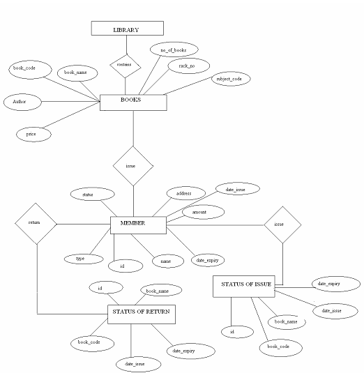
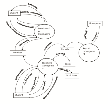
Data Flow Diagram (DFD)ঃ
Referencesঃ
We used many books and sites to complete our project
Books:
- Database by Frederick Eddy.
- Jason Gerner, Yann Le Scouaruec, Jeremy StolT. Michael K, Glass.
- The Fundamental of Database, by C.J. Date.
Web Sites:
- www.apache.org
- www.wikipedia.com
- www.w3school.com