Introduction
In past years, we purely lived on analog system. Both the sources and transmission system were on analog format but the advancement of technology made it possible to transmit data digitally. Broadband Wireless Access (BWA) has emerged as a promising solution for last mile access technology to provide high speed internet access in the residential as well as small and medium sized enterprise sectors. Applications like voice, Internet access, instant messaging, SMS, paging, file transferring, video conferencing, gaming and entertainment etc became a part of life. We can consider cellular phone systems, WLAN, wide-area wireless data systems, ad-hoc wireless networks and satellite systems etc as wireless communication. Wireless technology provide higher throughput, huge mobility, longer range, robust backbone to thereat. Engineers are trying to provide smooth transmission of multimedia anywhere on the globe through variety of applications and devices leading a new concept of wireless communication which is less expensive and flexible to implement even in odd environment.
Wireless Broadband Access (WBA) via DSL, T1-line or cable infrastructure is not available especially in rural or suburban areas. The DSL can covers only up to near about 18,000 feet (3 miles), this means that many urban, suburban, and rural areas may not served. The little-bit solution of this problem is to use Wi-Fi standard broadband connection but for coverage limitation its not possible in everywhere . But the Urban-area Wireless standard which is called WiMAX can solve these shortcoming. The wireless broadband connection is much easier to expose, have long range of coverage, easier to access and more flexible.
This connectivity is really important for developing countries and IEEE 802.16 family helps to solve the last mile connectivity problems with BWA connectivity. IEEE 802.16e can operate in both Line-Of-Sight (LOS) and Non-Line-Of-Sight (NLOS) environments. In NLOS, the PHY specification is extended to 211 GHz frequency band which aim is to fight with fading and multipath propagation. The OFDM physical layer based IEEE 802.16 standard is almost identical to European Telecommunications Standard Institute’s (ETSI) High performance Metropolitan Area Network (HiperMAN) as they cooperate with each other[1] .
This thesis is all about WiMAX OFDM PHY layer performance where we analyzed the results using MATLAB simulator with different modulation techniques.
1.2 Why WiMAX
WiMAX is the next generation broadband wireless technology. It offers high speed, secure, sophisticate and last mile broadband services along with a cellular pull back and Wi-Fi hotspots. The evolution of WiMAX began shortly when scientists and engineers felt the importance of having a wireless Internet access and other broadband services which works well in rural and urban areas and also in those areas where it is not possible to establish wired infrastructure. IEEE 802.16, also known as IEEE Wireless-MAN, explored both licensed and unlicensed band of 2-66 GHz which is standard of fixed wireless broadband and included mobile broadband application. WiMAX forum, a private organization was formed in June 2001 to coordinate the components and develop the equipment those will be compatible and inter operable. After several years, in 2007, Mobile WiMAX equipment developed with the standard IEEE 802.16e got the certification and they announced to release the product in 2008, providing mobility and nomadic access. The IEEE 802.16e air interface based on Orthogonal Frequency Division Multiple Access (OFDMA) which main aim is to give better performance in non-line-of-sight environments. IEEE 802.16e introduced scalable channel bandwidth up to 20 MHz, Multiple Input Multiple Output (MIMO) and AMC enabled 802.16e technology to support peak Downlink (DL) data rates up to 63 Mbps in a 20 MHz channel through Scalable OFDMA (S-OFDMA) system. IEEE 802.16e has strong security architecture as it uses Extensible Authentication Protocol (EAP) for mutual authentication, a series of strong encryption algorithms, CMAC or HMAC based message protection and reduced key lifetime.
1.3 Fixed Vs Mobile WiMAX
There are certain differences between Fixed WiMAX and Mobile WiMAX. 802.16d is known as Fixed WiMAX and 802.16e standard is fondly referred as Mobile-WiMAX. The 802.16d standard supports fixed and nomadic applications whereas 802.16e standard supports fixed, nomadic, mobile and portable applications. The 802.16e carries all the features of 802.16d standard along with new specifications that enables full mobility at vehicular speed, better QoS performance and power control but 802.16e devices are not compatible with 802.16d base stations as 802.16e based on TDD whereas 802.16d is on FDD. Due to other compatibility issues with existing networks, 802.16e adopted S-OFDMA and 2048-FFT size. The main aim of mobile WiMAX is to support roaming capability and handover between Mobile Station (MS) and Base Station (BS) [2]. Several countries have already planned Mobile WiMAX for commercial services. The development included some new features on the link layer. Such features are, different types of handover techniques, robust power saving system and multiple broadcast supports etc.
1.4 WiMAX’s Path to Overcome
There are several challenges for WiMAX. These important issues must be solved to fulfill its dream of last mile solution. Some of those are mentioned below.
1.4.1 PAL and PAPR
OFDM has high Peak to Average Power Ratio. A recent analysis of its waveform showed a large fluctuation in its amplitude which leads to a huge challenge to design a power amplifier with adequate power back-off. To do so, it has to focus on different situations like, good sensitivity when the power is low, tolerability to high power level and tracking ability to track down changes. Clipping and coding have been used to fight with these effects but still researches needed in that issue to make it a good wireless communication system.
1.4.2 Attenuation
Each signal has a specific potency. To reach to a distant receiver, a signal must be strong enough to be detected by the receiver. When a signal travels in the air, gradually it becomes weaker over time and this phenomenon is called Attenuation. WiMAX is considering this issue carefully as it works on both LOS and NLOS environment.
1.4.3 Multi Path Fading
When an object comes on the way between a wireless transmitter and a receiver, it blocks the signal and creates several signal paths known as multi path. Even though the signal makes till the receiver but with variant time and it is hard to detect the actual signal. Multi path degrade the quality of the signal. Several multipath barriers which as follow:
- Fast Fading
Rapid changes in signal power occur when distance moves about a half wave length. It is build up by constructive and destructive Interference. This fading occurs when the coherence time is less than the each symbol period and the Doppler spread spectrum is high in the channel.
- Slow Fading
Changes in average received signal power due to the changing distance between transmitter and the receiver or changes of surroundings when moving. This fading occurs when the coherence time is greater than the each symbol period and the Doppler spread spectrum is low in the channel.
- Flat Fading (Non-Selective Fading)
Flat fading is that type of fading in which all frequency components of the received signal fluctuates simultaneously in the same proportion[3].This fading occurs when the channel bandwidth and delay spread spectrum of a signal is less than the channel bandwidth and symbol period.
- Frequency Selective Fading
Selective fading affects unequally the different spectral components of a radio signal[3]. This fading occurs when the channel bandwidth and delay spread spectrum of a signal is greater than the channel bandwidth and symbol period.
- Rayleigh Fading
NLOS (indoor, city) Rayleigh fading occurs when there is no multipath LOS between transmitter and receiver and have only indirect path which is called NLOS to receive the resultant waves[3].
- Rician Fading
Rician fading best characterizes a situation where there is a direct LOS path in addition to a number of indirect multipath signals between the transmitter and receiver.
1.4.4 Noise
Different types of noises create problem in wireless communication which hampers the transmission quality. Best known noises in wireless media are:
- Thermal Noise
It occurs due to agitation of electrons and it is present in all electronic devices and transmission media such as transmitter, channels, repeaters and receiver. It is more significant in satellite communication[4].
Principle equation:
N0 = KT (W/Hz) ——————————————————————————— (1.1)
Where: N0= noise power density in watts per 1 Hz of bandwidth K = Boltzmann’s constant = 1.3803 ´10-23J/K T = temperature, in Kelvin (absolute temperature)
If the noise is assumed as independent, the thermal noise present in a bandwidth of B Hertz (in watts):
N= KTB ———————————– ———————————————- (1.2)
Or, in decibel-watts,
N=10 log k+ 10log T +10log B = -228.6 dbW+10log T +10log B ——————(1.3)
- Inter-modulation noise
It occurs if the medium has non-linearity. Interference caused by signals produced at frequencies that are the sum or variety of original frequencies.
- Inter Symbol Interference (ISI)
At the same time all delayed copies in a pulse may arrive as primary pulse for a subsequent bit.
- Cross Talk
If there are unwanted coupling found in a signal path, it is called cross talk. It creates so many problems in communication media.
- Impulse Noise
When irregular pulses or noise spikes occurs due to external electromagnetic disturbances, or faults and flaws in the communications system that is called impulse noise. The behavior of this type of noise has short duration and relatively high amplitude.
- Doppler Shift Effect
Doppler shift occurs when a mobile user move towards or away from the transmitter. It has huge impact on carrier frequency causing the communication poor in performance and increasing error probability.
Chapter-2
Wi-Max Architecture
2.1 Evolution of IEEE family of standard for BWA:
The IEEE standard committee introduced standards for networking elements, for an instance, IEEE 802.16 in 1999. The 802.16 family standard is introduced as Wireless Metropolitan Area Network (MAN) commercially known as WiMAX (Worldwide interoperability for Microwave Access) which is an nonprofit, industry-led organization and responsible for certificating, testing, and promoting the compatible interoperable wireless products based on IEEE 802.16 working group and ETSI’s HiperMAN standard. The original IEEE standard addressed 10 to 66 GHz in licensed bands and 2 to 11 GHz in unlicensed frequency range. They certified different versions of WiMAX based on different criteria such as carrier based wireless (single and multi carrier), fixed and portable wireless devices etc.
2.2 IEEE 802.16 versions
2.2.1 802.16
The first 802.16 standard was released in December 2000. It provides a standard point-to-multipoint broadcast in 10 to 66 GHz frequency range for Line of Sight (LOS) environment.
2.2.2 802.16a
The second version of WiMAX standard 802.16a was an amendment of 802.16 standard and has the capability to broadcast point-to-multipoint in the frequency range 2 to 11 GHz. It was established in January 2003 and assigned both licensed and unlicensed frequency bands. Unlicensed bands cover maximum distance from 31 to 50 miles. It improves the Quality of Service (QoS) features with supporting protocols for instance Ethernet, ATM or IP.
2.2.3 802.16c
The third version of WiMAX standard 802.16c was also an amendment of 802.16 standards which mostly dealt with frequency ranging 10 to 66 GHz. This standard addressed various issues, for instance, performance evaluation, testing and detailed system profiling. The system profile is developed to specify the mandatory features to ensure interoperability and the optional features that differentiate products by pricing and functionality.
2.2.4 802.16d
In September 2003, a revision project known as 802.16d began which aimed to align with a particular view of European Telecommunications Standards Institute (ETSI) Hiper-MAN. This project was deduced in 2004 with the release of 802.16d-2004 including all previous Performance Evaluation of IEEE 802.16e (Mobile WiMAX) in OFDM Physical versions’ amendments. This standard supports mandatory and optional elements along with TDD and FDD technologies. Theoretically, its effective data rate is 70 Mbps but in reality, the performance is near about 40 Mbps. This standard improves the Quality of Service (QoS) by supporting very large Service Data Units (SDU) and multiple polling schemes.
2.2.5 802.16e
802.16e was an amendment of 802.16d standard which finished in 2005 and known as 802.16e-2005. Its main aim is mobility including large range of coverage. Sometimes it is called mobile WiMAX. This standard is a technical updates of fixed WiMAX which has robust support of mobile broadband. Mobile WiMAX was built on Orthogonal Frequency Division Multiple Access (OFDMA). It mentioned that, both standards (802.16d-2004 and 802.16e-2005) support the 256-FFT size. The OFDMA system divides signals into sub-channels to enlarge resistance to multipath interference. For instance, if a 30 MHz channel is divided into 1000 sub-channels, each user would concede some sub-channels which are based on distance.
Table 2.1: Comparison of IEEE standard for BWA
IEEE 802.16 | IEEE 802.16a | IEEE802.16 | IEEE 802.16e | |
Completed | December 2001 | January 2003 | June 2004 | December 2005 |
Spectrum | 10-66 GHz | 2-11 GHz | 2-11 GHz | 2-6 GHz |
Popagation/channel conditions | LOS | NLOS | NLOS | NLOS |
Bit Rate | Up to 134 Mbps (28 MHz channelization) | Up to 75 Mbps (20 MHz channelization) | Up to 75 Mbps (20 MHz channelization) | Up to 15Mbps (5 MHz channelization) |
Modulation | QPSK, 16-QAM (optional in UL), 64-QAM (optional) | BPSK, QPSK, 16-QAM, 64-QAM, 256-QAM (optional) | 256 subcarriers OFDM, BPSK, QPSK, 16-QAM, 64-QAM, 256-QAM | Scalable OFDMA, QPSK, 16-QAM, 64-QAM, 256-QAM (optional) |
Mobility | Fixed | Fixed | Fixed | Fixed |
2.3 Features of WiMAX
There are certain features of WiMAX those are making it popular day by day. Some important features of WiMAX are described below:
2.3.1 Interoperability
This is the main concern of WiMAX. The IEEE 802.16 standard is internationally accepted and the standard is maintained and certified by WiMAX forum which covers fixed, portable and mobile deployments and giving the user the freedom to choose their product from different certified vendors and use it in different fixed, portable or mobile networks.
2.3.2 Long Range
Another main feature of WiMAX is long range of coverage. Theoretically, it covers up to 30 miles but in practice, it covers only 6 miles. The earlier versions of WiMAX provide LOS coverage but as technology advanced and the later version of WiMAX, e.g. mobile WiMAX, can support both LOS and NLOS connections. For that, it must meet the condition of the range for LOS, 50 kilometers and for NLOS, 10 kilometers. The WiMAX subscriber may connect to WiMAX Base station by Stanford University Interim (SUI) traffic model from their offices, homes, hotels and so on.
2.3.3 Mobility
WiMAX offers immense mobility especially IEEE 802.16e-2005 as it adopted SOFDMA (Scalable Orthogonal Frequency Division Multiple Access) as a modulation technique and MIMO (Multiple Input Multiple Output) in its physical layer. There are two challenges in wireless connectivity, one of them is for session initiation, which provides a mean to reach to inactive users and continue the connection service by extending it even the home location of that user has been changed and the other one provides an ongoing session without interruption while on moving (specially at vehicular speed). The first is known as roaming and the second one is handoff. These two are described below.
- Roaming
The centralized database keeps current information which sends to the network by the user base station when it moves from one location to another. To reach another subscriber station the network pages for it using another base station. The used subscriber station for paging depends on updating rate and movement of subscriber station – that means from one station to another. To perform this operation, there are several networking entities involved such as NSS (Network Switching Subsystem), HLR (Home Location Register) and VLR (Visitor Location Register) etc.
- NSS (localization and updating of location)
- HLR (contains information of current location) and
- VLR (sends information to Mobile Station to inform HLR about the changes of location)
- Handoff
Due to the absence of handoff technique, the Wi-Fi users may move around a building or a hotspot and be connected but if the users leave their location, they lose their connectivity. But with the 802.16e-2005, the mobile users will be connected through Wi-Fi when they are within a hotspot and then will be connected to 802.16 if they leave the hotspot but will stay in the WiMAX coverage area.
2.3.4 Quality of Service
Quality of Service (QoS) refers to the collective effect of service perceived by the users. Actually it refers to some particular requirements such as throughput, packet error rate, delay, and jitters etc. The wireless network must support a variety of applications for instance, voice, data, video, and multimedia. Each of these has different traffic pattern and requirements which is shown in the Table 2.2 [3].
Table 2.2: Sample Traffic Parameters for Broadband Wireless Application [3]
| Parameter | Interactive Gaming | Voice | Streaming Media | Data | Video |
| Data rate | 50Kbps to 85Kbps | 4Kbps-64Kbps | 5Kbps-384Kbps | 0.01Mbps-100Mbps | > 1Mbps |
| Applications | Interactive gaming | VoIP | Music, Speech, Video Clips | Web browsing, e-mail, instant messaging, telnet, file download | IPTV, movie download, p2p video sharing |
| Packet loss | Zero | <1% | <1% Audio <2% Video | Zero | <10-8 |
| Delay Variation | Not Applicable | <20ms | <2sec | Not Applicable | <2sec |
| Delay | <50ms-150ms | <100ms | <250ms | Flexible | <100ms |
2.3.5 Interfacing
Interface installation is another feature of WiMAX. Each base station broadcasts radio signals to its subscribers to stay with connection. Since each base station covers limited range so it is necessary to install multiple base stations after a certain distance to increase the range for network connectivity. Connecting multiple base stations is not a big deal and it takes only a few hours.
2.3.6 Accessibility
To get high speed network connectivity, only necessary thing is to become a subscriber of WiMAX service providers. Then they will provide hardware that is very easy to install. Most of time hardware connects through USB ports or Ethernet and the connection may be made by clicking button.
2.3.7 Scalability
802.16 standard supports flexible channel bandwidths for summarize cell planning in both licensed and unlicensed spectrum. If an operator assigned 15 MHz of spectrum, it can be divided into three sectors of 5MHz each. By increasing sector, the operator can increase the number of subscriber to provide better coverage and throughput. For an instance, 50 of hotspot subscribers are trying to get the network connectivity in a conference for 3 days. They also require internet access connectivity to their corporate network via Virtual Private Network (VPN) with T1 connection. For this connectivity, bandwidth is a big question as it needs more bandwidth. But in wireless broadband access it’s feasible to provide service to that location for a small period of time. It would be very hard to provide through wired connection. Even the operator may re-use the spectrum in three or more sectors by creating appropriate isolation.
2.3.8 Portability
Portability is another feature as like mobility that is offered by WiMAX. It is not only offers mobility applications but also offers nomadic access applications.
2.3.9 Last Mile Connectivity
Wireless network accesses via DSL, T1-line or cable infrastructure are not available especially in rural areas. These connections have more limitations which can be solved by WiMAX standards.
2.3.10 Robust Security
WiMAX have a robust privacy and key management protocol as it uses Advanced Encryption Standard (AES) which provides robust encryption policy. It also supports flexible authentication architecture which is based on Extensible Authentication Protocol (EAP) which allows variety of subscriber credentials including subscriber’s username and password, digital certificates and cards.
2.4 WiMAX Architecture
WiMAX architecture comprises of several components but the basic two components are BS and SS. Other components are MS, ASN, CSN and CSN-GW etc. The WiMAX Forum’s Network Working Group (NWG) has developed a network reference model according to the IEEE 802.16e-2005 air interface to make sure the objectives of WiMAX are achieved. To support fixed, nomadic and mobile WiMAX network, the network reference model can be logically divided into three parts[5].
- Mobile Station (MS)
It is for the end user to access the mobile network. It is a portable station able to move to wide areas and perform data and voice communication. It has all the necessary user equipments such as an antenna, amplifier, transmitter, receiver and software needed to perform the wireless communication. GSM, FDMA, TDMA, CDMA and W-CDMA devices etc are the examples of Mobile station.
- Access Service Network (ASN)
It is owned by NAP, formed with one or several base stations and ASN gateways (ASN-GW) which creates radio access network. It provides all the access services with full mobility and efficient scalability. Its ASN-GW controls the access in the network and coordinates between data and networking elements.
- Connectivity Service Network (CSN):
Provides IP connectivity to the Internet or other public or corporate networks. It also applies per user policy management, address management, location management between ASN, ensures QoS, roaming and security.

Fig 2.1: WiMAX Network Architecture based on IP
2.5 Mechanism
WiMAX is capable of working in different frequency ranges but according to the IEEE 802.16, the frequency band is 10 GHz – 66 GHz. A typical architecture of WiMAX includes a base station built on top of a high rise building and communicates on point to multi-point basis with subscriber stations which can be a business organization or a home. The base station is connected through Customer Premise Equipment (CPE) with the customer. This connection could be a Line-of-Sight (LOS) or Non-Line-of-Sight (NLOS).
2.5.1 Line of Sight (LOS)
In LOS connection, signal travels in a straight line which is free of obstacles, means, a direct connection between a transmitter and a receiver. The features of LOS connections are,
- Uses higher frequency between 10 GHz to 66 GHz
- Huge coverage areas
- Higher throughput
- Less interference
- Threat only comes from atmosphere and the characteristic of the frequency
- LOS requires most of its first Fresnel zone should be free of obstacles

Fig 2.2: WiMAX in LOS Condition
2.5.2 Non-Line of Sight (NLOS)
In NLOS connection, signal experiences obstacles in its path and reaches to the receiver through several reflections, refractions, diffractions, absorptions and scattering etc. These signals arrive to the receiver in different times, attenuation and strength which make it hard to detect the actual signal[6]. WiMAX offers other benefits which works well in NLOS condition,
- Frequency selective fading can be overcome by applying adaptive equalization
- Adaptive Modulation and Coding (AMC), AAS and MIMO techniques helps WiMAX to works efficiently in NLOS condition
- Sub-channelization permits to transmit appropriate power on sub-channels
- Based on the required data rate and channel condition, AMC provides the accurate modulation and code dynamically

2.6 Major shortcomings of WiMAX
There are several major shortcomings of WiMAX which are still a headache to the engineers. Those are as follows:
- Bit Error Rate
General concept of WiMAX is that, it provides high speed data rate within its maximum range (30 miles). If WiMAX operates the radio signals to its maximum range then the Bit Error Rate (BER) increases. So, it is better to use lower bit rates within short range to get higher data rates.
- Data Rates
Mobile WiMAX uses Customer Premises Equipment (CPE) which is attached to computers (either desktop or laptop or PDA) and a lower gain Omni-directional antenna is installed which is difficult to use compared to fixed WiMAX.
- LOS and NLOS coverage
Mobile WiMAX covers 10 kilometers with 10 Mbps speeds in line -of-sight (LOS) environment but in urban areas, it is only 2 kilometers coverage due to non-line-of-sight problem. In this situation, mobile WiMAX may use higher gain directional antenna for excellent coverage and throughput but problem is that it loose its mobility.
Besides all above shortcomings, there is a major impact of weather conditions like rain, fog and droughts etc on WiMAX networks.
2.7 IEEE 802.16 Protocol Layers
IEEE 802.16 standard WiMAX gives freedom in several things compared to other technologies. The focus is not only on transmitting tens of megabits of data to many miles distances but also maintaining effective QoS (Quality of Services) and security. This chapter gives an overview of IEEE 802.16 protocol layers and OFDM features. WiMAX 802.16 is mainly based on the physical and data link layer in OSI reference model. Here, Physical layer can be single-carrier or multi-carrier (PHY) based and its data link layer is subdivided into two layers
- Logical Link Control (LLC) and
- Medium Access Control (MAC)
MAC is further divided into three sub-layers:
- Convergence Sub-layer (CS)
- Common Part Sub-layer (CPS) and
- Security Sub-layer (SS).
2.7.1 Physical Layer (PHY)
Physical layer set up the connection between the communicating devices and is responsible for transmitting the bit sequence. It also defines the type of modulation and demodulation as well as transmission power. WiMAX 802.16 physical layer considers two types of transmission techniques OFDM and OFDMA. Both of these techniques have frequency band below 11 GHz and use TDD and FDD as its duplexing technology. After implementing OFDM in IEEE 802.16d, OFDMA has been included in IEEE 802.16e to provide support in NLOS conditions and mobility. The earlier version uses 10 to 66 GHz but the later version is expanded to use up the lower bandwidth from 2 to 11 GHz which also supports the 10 to 66 GHz frequency bands. There are some mandatory and some optional features included with the physical layer specification.

Fig 2.4: WiMAX Physical and MAC layer architecture
From OSI 7 layer reference model, WiMAX only uses the physical layer and MAC of datalink layer.
There are specific names for each physical layer interface. The Table summarizes IEEE 802.16 physical layer’s features.
Table 2.3: IEEE 802.16 standard air interface’s description
| Specific Name | Operating Band | Duplexing |
| ||
| WirelessMAN-SC™ | 10 to 66 GHz | FDD and TDD | Single-carrier | ||
| WirelessMAN-SCa™ | 2 to 11 GHz, Licensed | FDD and TDD | Single-carrier, NLOS | ||
| WirelessMAN-OFDMA™ | 2 to 11 GHz, Licensed | FDD and TDD | OFDM technique, NLOS | ||
| WirelessHUMAN™ | 2 to 11 GHz, Free | TDD | Single-carrier, LOS, NLOS, OFDM, OFDMA, Frequency selective channel | ||
| WirelessMAN-OFDMA™ | 2 to 11 GHz, Licensed | FDD and TDD | Single frequency band, OFDM system divides signal into sub-channels |
2.7.2 MAC layer
The basic task of WiMAX MAC is to provide an interface between the physical layer and the upper transport layer. It takes a special packet called MAC Service Data Units (MSDUs) from the upper layer and makes those suitable to transmit over the air. For receiving purpose, the mechanism of MAC is just the reverse. In both fixed and mobile WiMAX, it included a convergence sub-layer which is able to interface with upper layer protocols such as ATM, TDM, Voice and other advanced protocols. WiMAX MAC has unique features to identify and address the SS and BS. Each SS carries 48-bit IEEE MAC address whereas BS carries 48-bit Base Station ID in which 24-bit uses for operator indicator. Other features are, 16-bit CID, 16-bit SAID and 32-bit SFID. MAC supports a variety of applications and mobility features such as,
- PKM for MAC security and PKMV2 for Extensible Authentication Protocol (EAP)
- Fast handover and strong mobility management
- Provides normal, sleep and idle mode power levels
2.7.3 Sub-layers
WiMAX MAC layer is divided into three sub-layers such as Service Specific Convergence Sub-layer (SSCS), Common Part Sub-layer (CPS) and Security Sub-layer (SS).

Fig 2.5: Purposes of MAC Layer in WiMAX
2.7.4 Service Specific Convergence Sub-layer (SSCS)
This stays on the top of MAC layer architecture which takes data from the upper layer entities such as router and bridges. It is a sub-layer that is service dependent and assures data transmission. It enables QoS and bandwidth allocation. Payload header suppression and increase the link efficiency are other important task of this layer. IEEE 802.16 specifies two types of SSCS for mapping function.
- ATM Convergence sub-layer: is a logical interface which is responsible for Asynchronous Transfer Mode (ATM) services. In the operation, it accepts ATM cells from ATM layer classify and then sends CS PDUs to MAC SAP. It differentiates Virtual path switched ATM connection and assigns Channel ID (CID)
- Packet Convergence sub-layer: It’s a packet based protocol which performs packet mapping such as IP, IPv4, IPv6, IEEE 802.3 Ethernet LAN, VLAN and PPP.
2.7.5 Common Part Sub-layer (CPS)
It stays underneath of SSCS and above the Security Sub-layer and defines the multiple access mechanism. CPS is responsible for the major MAC functionalities like system access, establishing the connection and maintain and bandwidth management etc. As WiMAX MAC is connection oriented so it provides service flows after each Subscriber Station’s registration. Other responsibilities are, providing QoS for service flows and managing connection by adding or deleting or modifying the connection statically or dynamically. On downlink channel, only the BS transmits and it does not need any coordination function. SS receives only those messages which are addressed to them. On uplink channel, three major principles defines the transmission right[7],
- Unsolicited bandwidth permission
- Polling and
- Contention procedures
2.7.6 Security Sub-layer (SS)
This part stays at the bottom of MAC layer and one of the most important part of MAC as it provides authentication, secure key exchange, encryption and integrity of the system. IEEE 802.16 standard defines both ways data encryption connection between subscriber and base station. A set of cryptographic suites such as data encryption and authentication algorithm has been defined which made security sub-layer of WiMAX MAC very robust. A secure distribution of keying data from base station to subscriber station is assured by providing an authentication and a PKM protocol. On top of that, in SS, the addition of a digital certificate strengthen the privacy of data and in BS, the PKM assured the conditional access to the network services and applications. Further improvement of PKM protocol is also defined with some additional features and with a new name named PKMv2 which strongly controls integrity, mutual authentication and handover mechanisms[8].
2.8 WiMAX forum and adaptation of IEEE 802.16
The Worldwide Interoperability for Microwave Access (WiMAX) forum is an alliance of telecommunication equipments and components manufacturers and service providers, formed to promote and certify the compatibility and interoperability of BWA products employing the IEEE 802.16 and ETSI HiperMAN[9] wireless specifications. WiMAX Forum Certified™[10] equipment is proven interoperable with other vendors’ equipment that is also WiMAX Forum Certified™. So far WiMAX forum has setup certification laboratories in Spain, Korea and China. Additionally, the WiMAX forum creates what it calls system profiles, which are specific implementations, selections of options within the standard, to suit particular ensembles of service offerings and subscriber populations[11]. WiMAX forum has adopted two version of the IEEE 802.16 standard to provide different types of access:
- Fixed/Nomadic access: The WiMAX forum has adopted IEEE802.162004 And ETSI HyperMAN standard for fixed and nomadic access[9]. This uses Orthogonal Frequency Division Multiplexing and able to provide supports in Line of Sight (LOS) and Non Line of Sight (NLOS) propagation environment. Both outdoor and indoor CPEs are available for fixed access. The main focus of the WiMAX forum profiles are on 3.5 GHz and 5.8 GHz frequency band.
- Portable/Mobile Access: The forum has adopted the IEEE 802.16e version of the standard, which has been optimized for mobile radio channels. This uses Scalable OFDM Access and provides support for handoffs and roaming[9]. IEEE 802.16e based network is also capable to provide fixed access. The WiMAX Mobile WiMAX profiles will cover 5, 7, 8.75, and 10 MHz channel bandwidths for licensed worldwide spectrum allocations in the 2.3 GHz, 2.5 GHz, 3.3 GHz and 3.5 GHz frequency bands[12]. The first certified product is expected to be available by the end of 2007.
2.9 Application of IEEE 802.16 based network:
IEEE 802.16 supports ATM, IPv4, IPv6, Ethernet and Virtual Local Area Network (VLAN) services [13]. SO, it can provide a rich choice of service possibilities to voice and data network service providers. It can be used for a wide selection of wireless broadband connection and solutions.
- Cellular Backhaul: IEEE 802.16 wireless technology can be an excellent choice for back haul for commercial enterprises such as hotspots as well as point to point back haul applications due to its robust bandwidth and long range.
- Residential Broadband: Practical limitations like long distance and lack off return channel prohibit many potential broadband customers reaching DSL and cable technologies [14]. IEEE 802.16 can fill the gaps in cable and DSL coverage.
- Underserved areas: In many rural areas, especially in developing countries, there is no existence of wired infrastructure. IEEE 802.16 can be a better solution to provide communication services to those areas using fixed CPE and high gained antenna.
- Always Best Connected: As IEEE 802.16e supports mobility [15], so the mobile user in the business areas can access high speed services through their IEEE 802.16/WiMAX enabled handheld devices like PDA, Pocket PC and smart phone.

Figure 2.6: Application scenarios
Chapter-3
Modulation
3.1 Modulation Techniques
The variation of the property of a signal, such as its amplitude, frequency or phase is called modulation. This process carries a digital signal or message. Different types of modulation techniques are available such as, Amplitude Shift Keying (ASK), Frequency Shift Keying (FSK) and Phase Shift Keying (PSK). This section discusses on different modulation techniques along with WiMAX’s special modulation technique which is called Adaptive Modulation technique.
3.2 ASK, FSK and PSK
Basic modulation techniques consist on three parts. Which as follows,
- Amplitude Shift Keying (ASK)
- Frequency Shift Keying (FSK)
- Phase Shift Keying (PSK)
3.2.1 Amplitude-Shift Keying (ASK)
Amplitude difference of carrier frequency is called ASK. In this, the phase and the frequency are always constant. The principle is based on the mathematical equation,

Features of ASK
- Likely to be affected by sudden changes of gain.
- Inefficient modulation technique compared to other techniques.
- On the voice transmission lines such as telephone, used up to 1200 bps.
- Use in optical fibres to transmit digital data.
3.2.2 Frequency Shift Keying (FSK)
Frequency difference near carrier frequency is called FSK. In this, the phase and the amplitude are always constant. There are several types of FSK. Most common are, Binary Frequency Shift Keying (BFSK) and Multiple Frequency Shift Keying (MFSK).
3.2.3 Binary Frequency Shift Keying (BFSK)
Two frequencies represent two binary values in this technique. The principle lies on the equation,

Features of BFSK
· Less affected by errors than ASK.
· On voice transmission lines such as telephone, range till 1200bps.
· Which is used for high-frequency (3 to 30 MHz) radio frequency.
· Suitable for LANs that use coaxial cables.
3.2.4 Multiple Frequency Shift Keying (MFSK)
More than two frequencies are used to represent signaling elements. The principle lies on the equations,

Features of MFSK
· Multiple frequencies are used
· More bandwidth efficient but very much affected by errors
· Bandwidth requirement is 2Mfd in total.
· Each signal element encodes L bits (M=2L).
3.2.5 Phase-Shift Keying (PSK)
Phase of carrier signal is digital modulation scheme which conveys data by modulating or changing of carrier wave. The most common and widely used are Binary Phase shift Keying (BPSK) and Quadrature Phase Shift Keying (QPSK). Other PSKs are Differential Phase Shift Keying (DPSK) and Multilevel Phase Shift Keying (MPSK) etc. As WiMAX uses Adaptive Modulation Techniques, so, here we will broadly discuss only BPSK, QPSK and QAM.
3.2.6 Binary Phase Shift Keying (BPSK)
This is also known as two-level PSK as it uses two phases separated by 180º to represent binary digits. The principle equation is,

This kind of phase modulation is very effective and robust against noises especially in low data rate applications as it can modulate only 1bit per symbol.

Fig 3.1: BPSK, (a) Block Diagram (b) Constellation
3.2.7 Quadrature Phase Shift Keying (QPSK)
This is also known as four-level PSK where each element represents more than one bit. Each symbol contains two bits and it uses the phase shift of π/2, means 90º instead of shifting the phase 180º. The principle equation of the technique is:

In this mechanism, the constellation consists of four points but the decision is always made in two bits. This mechanism can ensure the efficient use of bandwidth and higher spectral efficiency[16].
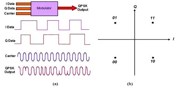
Fig 3.2: QPSK, (a) Block Diagram (b) Constellation
3.2.8 Quadrature Amplitude Modulation (QAM)
This is the most popular modulation technique used in various wireless standards. It combined with ASK and PSK which has two different signals sent concurrently on the same carrier frequency but one should be shifted by 90º with respect to the other signal. At the receiver end, the signals are demodulated and the results are combined to get the transmitted binary input [16]. The principle equation is:
![]()
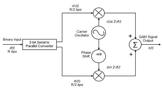
Fig 3.3: QAM Modulator Diagram
3.2.9 16-QAM
This is called 16-states Quadrature Amplitude Modulation which means four different amplitude levels would be used and the combined stream would be one of 16 = 4 * 4 states. In this mechanism, each symbol represents 4 bits[16].
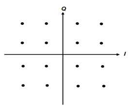
Fig 3.4: 16-QAM Constellation
3.2.10 64-QAM
This is same as 16-QAM except it has 64-states where each symbol represents six bits (26= 64). It is a complex modulation techniques but with greater efficiency [16]. The total bandwidth increases according to the increasing number of states for each symbol. Mobile WiMAX uses this higher modulation technique when the link condition is high.
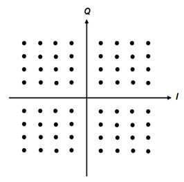
Fig 3.5: 64-QAM Constellation
3.3 Adaptive Modulation and Coding
The specified modulation scheme in the DL (DownLink) and UL( UpLink) are BPSK (Binary Phase Shift Keying) ,QPSK(Quadrature PSK), 16-QAM (16- Quadrature Amplitude Modulation) and 64-QAM to modulate bits to the complex constellation points. The FEC options are paired with the modulation schemes to form burst profiles. The PHY specifies seven combinations of modulation and coding rate, which can be allocated selectively to each subscriber, in both UL and DL [17]. There are tradeoffs between data rate and robustness, depending on the propagation conditions. Table 3.1 shows the combination of those modulation and coding rate.
Table 3.1: Mandatory channel coding per modulation
Modulation | Uncoded Block Size (bytes) | Coded Block Size (bytes) | Overall coding rate | RS code | CC code rate |
BPSK | 12 | 24 | 1/2 | (12,12,0) | 1/2 |
QPSK | 24 | 48 | 1/2 | (32,24,4) | 2/3 |
QPSK | 36 | 48 | 3/4 | (40,36,2) | 5/6 |
16-QAM | 48 | 96 | 1/2 | (64,48,8) | 2/3 |
16-QAM | 72 | 96 | 3/4 | (80,72,4) | 5/6 |
64-QAM | 96 | 144 | 2/3 | (108,96,6) | 3/4 |
64-QAM | 108 | 144 | 3/4 | (120,108,6) | 5/6 |
Chapter-4
Orthogonal Frequency Division Multiplexing
4.1 OFDM BASIC:
The idea of OFDM comes from Multi Carrier Modulation (MCM) transmission technique. The principle of MCM describes the division of input bit stream into several parallel bit streams and then they are used to modulate several sub carriers as shown in Figure 4.1. Each subcarrier is separated by a guard band to ensure that they do not overlap with each other. In the receiver side, bandpass filters are used to separate the spectrum of individual subcarriers. OFDM is a special form of spectrally efficient MCM technique, which employs densely spaced orthogonal subcarriers and overlapping spectrums. The use of bandpass filters are not required in OFDM because of the orthogonality nature of the subcarriers. Hence, the available bandwidth is used very efficiently without causing the InterCarrier Interference (ICI). In figure 4.2, the effect of this is seen as the required bandwidth is greatly reduced by removing guard band and allowing subcarrier to overlap. It is still possible to recover the individual subcarrier despite their overlapping spectrum provided that the orthogonality is maintained. The Orthogonality is achieved by performing Fast Fourier Transform (FFT) on the input stream. Because of the combination of multiple low data rate subcarriers, OFDM provides a composite high data rate with long symbol duration. Depending on the channel coherence time, this reduces or completely eliminates the risk of InterSymbol Interference (ISI), which is a common phenomenon in multipath channel environment with short symbol duration. The use of Cyclic Prefix (CP) in OFDM symbol can reduce the effect of ISI even more[18], but it also introduces a loss in SNR and data rate.
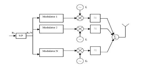
Figure 4.1: Block diagram of a generic MCM transmitter.
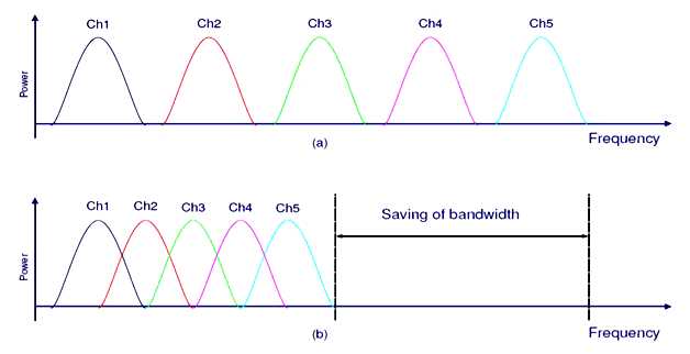
Figure 4.2: Comparison between conventional FDM and OFDM
4.2 OFDM SYSTEM IMPLEMENTATION
The principle of OFDM was already around in the 50’s and 60’s as an efficient MCM technique. But, the system implementation was delayed due to technological difficulties like digital implementation of FFT/IFFT, which were not possible to solve on that time. In 1965, Cooley and Tukey presented the algorithm for FFT calculation[19] and later its efficient implementation on chip makes the OFDM into application.
The digital implementation of OFDM system is achieved through the mathematical operations called Discrete Fourier Transform (DFT) and its counterpart Inverse Discrete Fourier Transform (IDFT). These two operations are extensively used for transforming data between the time domain and frequency domain. In case of OFDM, these transforms can be seen as mapping data onto orthogonal subcarriers.
In order to perform frequency domain data into time domain data, IDFT correlates the frequency domain input data with its orthogonal basis functions, which are sinusoids at certain frequencies. In other ways, this correlation is equivalent to mapping the input data onto the sinusoidal basis functions. In practice, OFDM systems employ combination of fast fourier transform (FFT) and Inverse fast Fourier transform (IFFT) blocks which are mathematical equivalent version of the DFT and IDFT.
At the transmitter side, an OFDM system treats the source symbols as though they are in the frequency domain. These symbols are feed to an IFFT block which brings the signal into the time domain. If the N numbers of subcarriers are chosen for the system, the basis functions for the IFFT are N orthogonal sinusoids of distinct frequency and IFFT receive N symbols at a time. Each of N complex valued input symbols determines both the amplitude and phase of the sinusoid for that subcarrier. The output of the IFFT is the summation of all N sinusoids and makes up a single OFDM symbol. The length of the OFDM symbol is NT where T is the IFFT input symbol period. In this way, IFFT block provides a simple way to modulate data onto N orthogonal subcarriers.
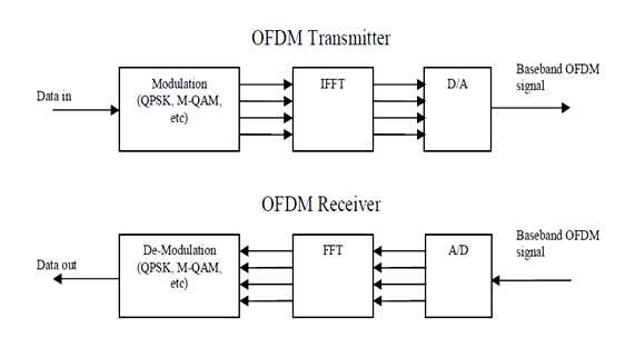
Figure 4.3: Basic OFDM transmitter and receiver
At the receiver side, The FFT block performs the reverse process on the received signal and bring it back to frequency domain. The block diagram in Figure 4.3 depicts the switch between frequency domain and time domain in an OFDM system.
4.3 Data transmission
Data transmission is high enough compared to FDM as OFDM follows multicarrier modulation. For this, OFDM splits high data bits into low data bits and sends each sub-stream in several parallel sub-channels, known as OFDM subcarriers. These subcarriers are orthogonal to each other and the each subcarrier bandwidth is much lesser than the total bandwidth. Inter Symbol Interference is reduced in OFDM technique as the symbol time Ts of each sub-channel is higher than the channel delay spread
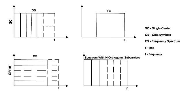
Fig 4.4: Time and Frequency diagram of Single and Multi-carrier signals
In the figure 4.4, it is clear that OFDM resists the multipath effect by adopting smaller frequency bandwidth and longer period of time which leads to get better spectral efficiency.
4.4 Parameters
The implementation of OFDM physical layer is different for two types of WiMAX. For fixed WiMAX, FFT size is fixed for OFDM-PHY and it is 256 but for mobile WiMAX, the FFT size for OFDMA-PHY can be 128, 512, 1024 and 2048 bits[1]. This helps to combat ISI and Doppler spread. Other difference between OFDM-PHY and OFDMA-PHY is, OFDM splits a single high bit rate data into several low bit rate of data sub-stream in parallel which are modulated by using IFFT whereas OFDMA accepts several users’ data and multiplex those onto downlink sub-channel. Uplink multiple access is provided through uplink sub-channel. OFDM-PHY and OFDMA-PHY parameters are discussed briefly in the following subsection.
4.4.1 OFDM-PHY
In this, FFT size is fixed and it is 256 bits in which number of used data subcarrier is 192, 8 pilot subcarriers to perform synchronization and channel estimation and 56 Null subcarriers [20]. The channel bandwidth for fixed WiMAX is 3.5 MHz but it varies due to spacing of subcarrier. Subcarrier spacing rises in higher bandwidth which decreases the symbol time eventually increases the delay spread. To avoid delay spreading, OFDM-PHY allocates a large fraction of guard space. For OFDM-PHY, the suitable symbol time is 64 μs, symbol duration is 72 μs and guard time spacing is 15.625 kHz[20].
4.4.2 OFDMA-PHY
In mobile WiMAX FFT size can varies between 128 and 2048 and to keep the subcarrier spacing at 10.94 KHz, the FFT size should be adjusted which is helpful to minimize Doppler spreads. Since there are different channel bandwidth like, 1.25, 5, 10 and 20 MHz etc, so FFT sizes are 128, 512, 1024 and 2048 respectively. For OFDMA-PHY, the suitable symbol time is 91.4 μs and the symbol duration is 102.9 μs and number of symbols in 5 ms frames is 48.0[20].
4.5 Sub-channelization
WiMAX divides the available subcarriers into several groups of subcarriers and allocates to different users based on channel conditions and requirement of users. This process is called sub-channelization. Sub-channeling concentrates the transmit power to different smaller groups of subcarrier to increase the system gain and widen up the coverage area with less penetration losses that cause by buildings and other obstacles. Without sub-channelization, the link budget would be asymmetric and bandwidth management would be poor[6]. Fixed WiMAX based OFDM-PHY permits a little amount of sub-channelization only on the uplink. Among 16 standard sub-channel, transmission can takes place in 1, 2, 4, 8 or all sets of sub-channels in the uplink of the SS. SS controls the transmitted power level up and down depending on allotted sub-channels. When the allotted sub-channels increase for uplink users, the transmitted power level increases and when the power level decreases, it means the allotted sub-channels decreased. The transmitted power level is always kept below the maximum level. In fixed WiMAX, to improve link budget and the performance of the battery of the SS, the uplink sub-channelization permits SS to transmit only a fraction of the bandwidth usually below 1/16 allocated by the BS[21].
Mobile WiMAX’s OFDMA-PHY permits sub-channelization in both uplink and downlink channels. The BS allocates the minimum frequency and sub-channels for different users based on multiple access technique. That is why this kind of OFDM is called OFDMA (Orthogonal Frequency Division Multiple Access). For mobile application, frequency diversity is provided by formation of distributed subcarriers. Mobile WiMAX has several distributed carrier based sub-channelization schemes. The mandatory one is called Partial Usage of Sub-Carrier (PUSC). Another sub-channelization scheme based on unbroken subcarrier is called Adaptive Modulation and Coding (AMC) in which multiuser diversity got the highest priority. In this, allocation of sub-channels to users is done based on their frequency response. It is a fact that, contiguous sub-channels are best suited for fixed and low mobility application, but it can give certain level of gain in overall system capacity[21].
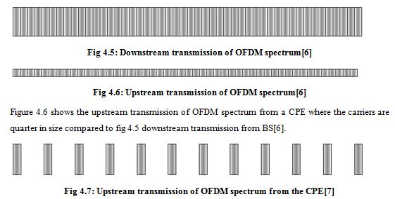
Figure 4.7 illustrates the transmitted upstream OFDM spectrum from a CPE where the carriers are as same as BS in size and range but with small capacity[6].
4.6 BENEFITS AND DRAWBACKS of OFDM:
In the earlier section, we have stated that how an OFDM system combats the ISI and reduces the ICI. Besides those benefits, there are some other benefits as follows:
· High spectral efficiency because of overlapping spectra
· Simple implementation by fast fourier transform
· Low receiver complexity as the transmitter combat the channel effect to some extends.
· Suitable for high datar ate transmission
· High flexibility in terms of link adaptation
· Low complexity multiple access schemes such as orthogonal frequency division multiple access (OFDMA)
· It is possible to use maximum likelihood detection with reasonable complexity[22].
On the other side, few drawbacks of OFDM are listed as follows
· An OFDM system is highly sensitive to timing and frequency offsets[18] . Demodulation of an OFDM signal with an offset in the frequency can lead to a high bit error rate.
· An OFDM system with large number of subcarriers will have a higher peak to average power ratio (PAPR) compared to single carrier system. High PAPR of a system makes the implementation of Digital to analog (DAC) and Analog to Digital Conversion (ADC) extremely difficult[23].
4.7 APPLICATION
OFDM has gained a big interest since the beginning of the 1990s[24] as many of the implementation difficulties have been overcome. OFDM has been in used or proposed for a number of wired and wireless applications. Digital Audio Broadcasting (DAB) was the first commercial use of OFDM technology[23]. OFDM has also been used for the Digital Video Broadcasting[25] . OFDM under the acronym of Discrete Multi Tone (DMT) has been selected for asymmetric digital subscriber line (ADSL)[26]. The specification for Wireless LAN standard such as IEEE 802.11a/g[27-28] and ETSI HIPERLAN2[29] has employed OFDM as their PHY technologies. IEEE 806.16 standard for Fixed/Mobile BWA has also accepted OFDM for PHY technologies.
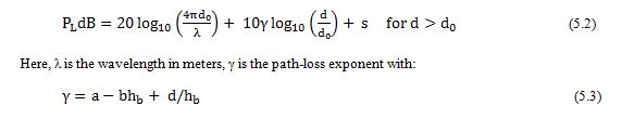
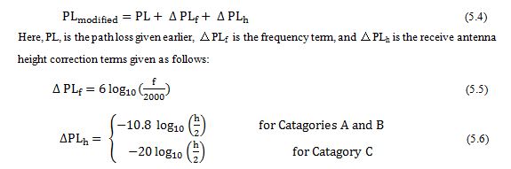
hb is the height of the base station in meters (between 10 m and 80 m), d0 = 100 m, and a, b, c are constants dependent on the terrain category. These parameters are listed in the table below.
Table 5.1: Parameters of the ERCEG model
Model Parameter | Terrain Type A | Terrain Type B | Terrain Type C |
a | 4.6 | 4 | 3.6 |
b | 0.0075 | 0.0065 | 0.005 |
c | 12.6 | 17.1 | 20 |
s represents the shadowing effect and follows a lognormal distribution with a typical standard
deviation of 8.2 to 10.6 dB.
The above model is valid for frequencies close to 2 GHz and for receive antenna heights close to 2 m. For other frequencies and antenna heights (between 2 m and 10 m), the following correction terms are recommended :
5.2.2 SUI Models
This is a set of 6 channel models representing three terrain types and a variety of Doppler spreads, delay spread and line-of-sight/non-line-of-site conditions that are typical of the continental US as follows[31]:
Table 5.2: Terrain type and Doppler spread for SUI channel model
Channel | Terrain type | Doppler Spread | Spread | LOS |
SUI-1 | C | Low | Low | High |
SUI-2 | C | Low | Low | High |
SUI-3 | B | Low | Low | High |
SUI-4 | B | High | Moderate | High |
SUI-5 | A | Low | High | Low |
SUI-6 | A | High | High | Low |
The terrain type A, B,C are same as those defined earlier for Erceg model. The multipath fading is modeled as a tapped delay line with 3 taps with non-uniform delays. The gain associated with each tap is characterized by a Rician Distribution and the maximum Doppler frequency. In a multipath environment, the received power r has a Rician distribution, whose pdf is given by:
![]()
Here, I0 (x) is the modified Bessel function of the first kind, zero order. A is zero if there is no LOS component and the pdf of the received power becomes:
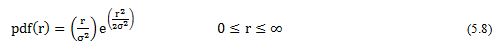
This is the Raleigh distribution. The ratioK = A2/(2σ2) in the Rician case represents the ratio of
LOS component to NLOS component and is called the “K-Factor” or “Rician Factor.” For NLOS case, K-factor is zero and the Rician distribution reduces to Raleigh Distribution.
The general structure for the SUI channel model is as shown below in Figure 5.1. This structure is for Multiple Input Multiple Output (MIMO) channels and includes other configurations like Single Input Single Output (SISO) and Single Input Multiple Output (SIMO) as subsets. The SUI channel structure is the same for the primary and interfering signals.
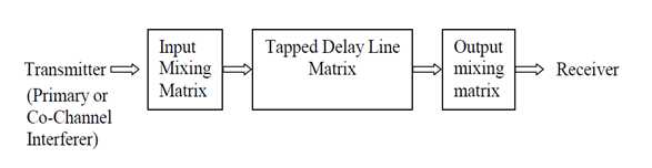
Figure 5.1:Generic Structure of SUI Channel Models
# Input Mixing Matrix
This part models correlation between input signals if multiple transmitting antennas are used.
# Tapped Delay Line Matrix
This part models the multipath fading of the channel. The multipath fading is modeled as a tapped delay line with 3 taps with non-uniform delays. The gain associated with each tap is characterized by a distribution (Rician with a K-factor > 0, or Raleigh with K-factor = 0) and the maximum Doppler frequency.
#Output Mixing Matrix
This part models the correlation between output signals if multiple receiving antennas are used. Using the above general structure of the SUI Channel and assuming the following scenario, six SUI channels are constructed which are representative of the real channels.
5.3 Scenario for modified SUI channels
Table 5.3: Scenario for SUI Channel Models
Cell size | 7 KM |
BTS Antenna Height | 30 m |
Receive Antenna Height | 6 m |
BTS Antenna Beam Width | 120o |
Receive Antenna Beam Width | Omni directional (360°) and 30°. |
Polarization | Vertical Polarization Only |
Cell coverage | 90% cell coverage with 99.9% reliability at each location covered. |
5.4 Characteristics of SUI Channels:
In the following models, the total channel gain is not normalized. Before using a SUI model, the specified normalization factors have to be added to each tap to arrive at 0dB total mean power. The specified Doppler is the maximum frequency parameter. The Gain Reduction Factor (GRF) is the total mean power reduction for a 30° antenna compared to an Omni antenna. If 30oantennas are used the specified GRF should be added to the path loss. Note that this implies that all 3 taps are affected equally due to effects of local scattering. K-factors have linear values, not dB values. K-factors for the 90% and 75% cell coverage are shown in the tables, i.e., 90% and 75% of the cell locations have K factors greater or equal to the K-factor value specified, respectively. For the SUI channels 5 and 6, 50% K-factor values are also shown.
Table 5.4: Characteristic of SUI-1
SUI – 1 Channel | |||||
| Tap 1 | Tap 2 | Tap 3 | Units | |
Delay | 0 | 0.4 | 0.9 | μs | |
Power (omni ant.) 90% K-fact.(omni) 75% K-fact.(omni)
|
0 4 20 |
-15 0 0 |
-20 0 0 | dB | |
Power (300 ant.) 90% K-fact.( 300) 75% K-fact.( 300) |
0 16 72 |
-21 0 0 |
-32 0 0 | dB | |
Doppler | 0.4 | 0.3 | 0.5 | Hz | |
Antenna Correlation: ρENV = 0.7 Gain Reduction Factor: GRF= 0 dB Normalization Factor: Fomni= -0.1771dB, F300 = -0.0371dB | Terrain Type: C Omni antenna: τRMS = 0.111 μs Overall K:K= 3.3(90%); K= 10.4(75%) 300 antenna: τRMS = 0.042 μs Overall K:K= 14.0(90%); K=44.2(75%) | ||||
Table 5.5: Characteristic of SUI-2
SUI – 2 Channel | |||||
| Tap 1 | Tap 2 | Tap 3 | Units | |
Delay | 0 | 0.4 | 1.1 | μs | |
Power (omni ant.) 90% K-fact.(omni) 75% K-fact.(omni)
|
0 2 11 |
-12 0 0 |
-15 0 0 | dB | |
Power (300 ant.) 90% K-fact.( 300) 75% K-fact.( 300) |
0 8 36 |
-18 0 0 |
-27 0 0 | dB | |
Doppler | 0.2 | 0.15 | 0.25 | Hz | |
Antenna Correlation: ρENV = 0.5 Gain Reduction Factor: GRF= 2 dB Normalization Factor: Fomni= -0.3930dB, F300 = -0.0768dB | Terrain Type: C Omni antenna: τRMS = 0.202 μs Overall K:K= 1.6(90%); K= 5.1(75%) 300 antenna: τRMS = 0.069 μs Overall K:K= 6.9(90%); K=21.8(75%) | ||||
Table 5.6:Characteristic of SUI-3
SUI – 3 Channel | |||||
| Tap 1 | Tap 2 | Tap 3 | Units | |
Delay | 0 | 0.4 | 0.9 | μs | |
Power (omni ant.) 90% K-fact.(omni) 75% K-fact.(omni)
|
0 1 7 |
-5 0 0 |
-10 0 0 | dB | |
Power (300 ant.) 90% K-fact.( 300) 75% K-fact.( 300) |
0 3 19 |
-11 0 0 |
-22 0 0 | dB | |
Doppler | 0.4 | 0.3 | 0.5 | Hz | |
Antenna Correlation: ρENV = 0.4 Gain Reduction Factor: GRF= 3 dB Normalization Factor: Fomni= -1.5113dB, F300 = -0.3573dB | Terrain Type: B Omni antenna: τRMS = 0.264 μs Overall K:K= 0.5(90%); K= 1.6(75%) 300 antenna: τRMS = 0.123 μs Overall K:K= 2.2(90%); K=7.0(75%) | ||||
Table 5.7:Characteristic of SUI-4
SUI – 4 Channel | |||||
| Tap 1 | Tap 2 | Tap 3 | Units | |
Delay | 0 | 1.5 | 4 | μs | |
Power (omni ant.) 90% K-fact.(omni) 75% K-fact.(omni)
|
0 0 1 |
-4 0 0 |
-8 0 0 | dB | |
Power (300 ant.) 90% K-fact.( 300) 75% K-fact.( 300) |
0 1 5 |
-10 0 0 |
-20 0 0 | dB | |
Doppler | 0.2 | 0.15 | 0.25 | Hz | |
Antenna Correlation: ρENV = 0.3 Gain Reduction Factor: GRF= 4 dB Normalization Factor: Fomni= -1.9218dB, F300 = -0.4532dB | Terrain Type: B Omni antenna: τRMS = 1.257 μs Overall K:K= 0.2(90%); K= 0.6(75%) 300 antenna: τRMS = 0.563 μs Overall K:K= 1.0(90%); K=3.2(75%) | ||||
Table 5.8: Characteristic of SUI-5
SUI – 5 Channel | |||||
| Tap 1 | Tap 2 | Tap 3 | Units | |
Delay | 0 | 4 | 10 | μs | |
Power (omni ant.) 90% K-fact.(omni) 75% K-fact.(omni) 50% K-fact.(omni) | 0 0 0 2 | -5 0 0 0 | -10 0 0 0 | dB | |
Power (300 ant.) 90% K-fact.( 300) 75% K-fact.( 300) 50% K-fact.( 300) | 0 0 2 7 | -11 0 0 0 | -22 0 0 0 | dB | |
Doppler | 2 | 1.5 | 2.5 | Hz | |
Antenna Correlation: ρENV = 0.3 Gain Reduction Factor: GRF= 4 dB Normalization Factor: Fomni= -1.5113dB, F300= -0.3573 dB | Terrain Type: A Omni antenna: τRMS = 2.842 μs Overall K:K= 0.1(90%); K=0.3(75%);K=1.0(50%) 300 antenna: τRMS = 1.276 μs Overall K:K= 0.4(90%); K=1.3(75%);K=4.2(50%) | ||||
Table 5.9:Characteristic of SUI-6
SUI – 6 Channel | |||||
| Tap 1 | Tap 2 | Tap 3 | Units | |
Delay | 0 | 14 | 20 | μs | |
Power (omni ant.) 90% K-fact.(omni) 75% K-fact.(omni) 50% K-fact.(omni) | 0 0 0 1 | -10 0 0 0 | -14 0 0 0 | dB | |
Power (300 ant.) 90% K-fact.( 300) 75% K-fact.( 300) 50% K-fact.( 300) | 0 0 2 5 | -16 0 0 0 | -26 0 0 0 | dB | |
Doppler | 0.4 | 0.3 | 0.5 | Hz | |
Antenna Correlation: ρENV = 0.3 Gain Reduction Factor: GRF= 4 dB Normalization Factor: Fomni= -0.5683dB, F300 = -0.1184 dB | Terrain Type: A Omni antenna: τRMS = 5.240 μs Overall K:K= 0.1(90%); K= 0.3(75%);K=1.0(50%) 300 antenna: τRMS = 2.370 μs Overall K:K= 0.4(90%); K=1.3(75%);K=4.2(50%) | ||||
Chapter-6
Simulation Model
This chapter describes the simulation part of the thesis. A brief description of time and frequency division duplex is described first and then the simulation procedure is explained step by step with appropriate diagrams. We have employed Matlab 9.0 to develop the simulator. Before going for the physical layer setup, let us first define the OFDM symbol parameter used in our study.
6.1 Physical Layer Setup
Basically physical layer handles error correction and signal connectivity, as well as registration, initial ranging, connectivity channels and bandwidth request for data and management. Physical layer consists of some sequence of equal length frames which transmit through modulation and coding of RF signals. OFDM technology has been using by WiMAX technology. Different user assigning different sub carries which are allowed in orthogonal frequency division multiplexing (OFDM) techniques. It is durable to multi-path which helps to overcome multipath signals hitting the receiver. OFDM signals divide into 256 carries in IEEE-802.16 standard and IEEE 802.16e use scalable OFDMA. Wide range of frequencies supported by IEEE 802.16 standard and physical layer contains several multiplexing and modulation forms. Modulation methods in the uplink (UL) and downlink (DL) are Binary Phase Shift Keying (BPSK), Quadrature Phase Shift Keying (QPSK) and Quadrature Amplitude Modulation (QAM).
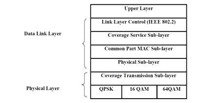
Fig 6.1: IEEE 802.16 Protocol Layer (IEEE-2004)
WiMAX supports both full and half duplex. Two types of transmission supported by IEEE 802.16,
§ Time Division Duplex (TDD)
§ Frequency Division Duplex (FDD)
6.1.1 Time Division Duplex (TDD)
Time division duplex framing is adaptive (when input changes it output behavior is automatically change). It consists fixed duration which consists one downlink frame and uplink frame. Base station (BS) sends complete downlink (DL-MAP, UL-MAP). Up and Down link share same frequency but they are separated in time.
6.1.2 Frequency Division Duplex (FDD)
During transmission in frequency division, multi-path is scheduled by DL-MAP and UL-MAP. Downlink and uplink can be done in same time, but on different frequency. UL and DL channels grouped into some continuous blocks of some paired channel. FDD system provide full duplex where we can make some application like voice, where DL and UP traffic requirement need more or less symmetric. In Base station (BS) to base station interface kept in minimum, in this technique, network for radio communication planning is easier.
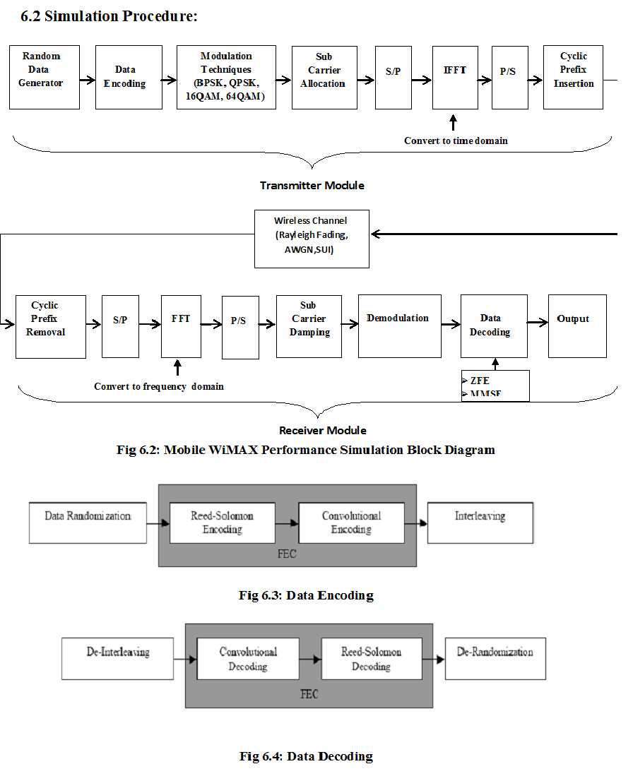
Block diagram 6.2 shows the whole process of the thesis work. Every part of the diagram is described below:
6.3 Transmitter Module
This subsection describes the transmitter module used for the simulation.
6.3.1 Mersenne Twister-Random Number Generator Algorithm
Mersenne Twister is a pseudo random number generator that produces a sequence of zeros and one bits. It might be combined into sub-sequences of zeros and ones or blocks of random numbers. There are two types of random number which is called deterministic and nondeterministic. We are dealing deterministic random numbers. A deterministic Random Number Generator (RNG) produces a sequence of bits from an initial value which is called seed. The seed value is 19,937 bits long and stored in 624 element array. The RNG algorithm has a period of 2**19937-1. A Pseudo Random Number Generator (PRNG) produces values based on a seed and current values. In our simulation we used this algorithm as function rand () to generate the random input value for evaluate the performance of WiMAX.
6.3.2 Modulation
We passed the random values through the adaptive modulation schemes according to the constellation mapped. The data was modulated depending their size and on the basis of different modulation schemes like BPSK, QPSK, 16-QAM and 64-QAM. The modulation has done on the basis of incoming bits by dividing among the groups of i. That is why there are 2i points. The total number of bits represented according to constellation mapped of different modulation techniques. The size of i for BPSK, QPSK, 16-QAM and 64-QAM is 1, 2, 4 and 16 respectively.
6.3.3 ReedSolomon Encoder
The randomized data are arranged in block format before passing through the encoder and a single 0X00 tail byte is appended to the end of each burst. The implemented RS encoder is derived from a systematic RS (N=255, K=239, T=8) code using GF (28). The following polynomials are used for code generator and field generator:
G(x) = (x+λ0)( x+λ0)… (x+λ2T-1), λ = 02HEX ———————————————(6.1)
p(x) = x8 + x4 + x3 + x2 + 1 —————————————————————-(6.2)
The encoder support shortened and punctured code to facilitate variable block sizes and variable error correction capability. A shortened block of k´ bytes is obtained through adding 239k´ zero bytes before
the data block and after encoding, these 239k´ zero bytes are discarded. To obtain the punctured pattern to permit T´ bytes to be corrected, the first 2T´ of the 16 parity bytes has been retained.
6.3.4 Convolutional Encoder
The outer RS encoded block is fed to inner binary convolutional encoder. The implemented encoder has native rate of 1/2, a constraint length of 7 and the generator polynomial in Equation (6.3) and (6.4) to produce its two code bits. The generator is shown in Figure 6.5.
G1 = 171OCT For X ——————————————————————————(6.3)
G2 = 133OCT For Y ——————————————————————————–(6.4)
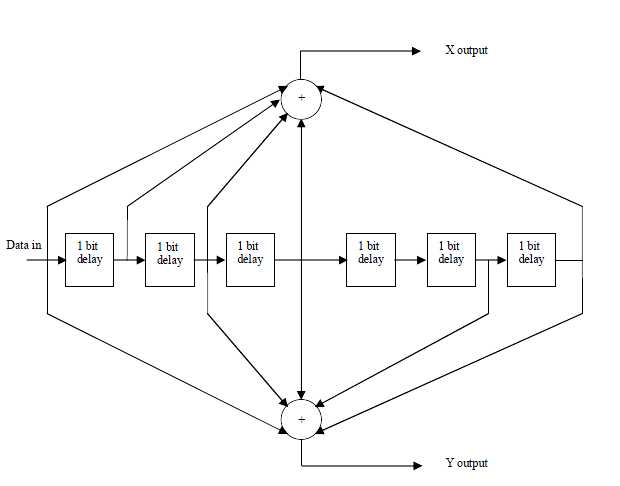
Figure 6.5: Convolutional encoder of rate ½
Table 6.1: Puncturing configuration of the convolution code
Rate | dFREE | X output | Y output | XY(punctured output) |
1/2 | 10 | 1 | 1 | X1Y1 |
2/3 | 6 | 10 | 11 | X1Y1Y2 |
3/4 | 5 | 101 | 110 | X1Y1Y2X3 |
5/6 | 4 | 10101 | 11010 | X1Y1Y2X3Y4X5 |
In order to achieve variable code rate a puncturing operation is performed on the output of the convolutional encoder in accordance to Table 6.1. In this Table “1” denotes that the corresponding convolutional encoder output is used, while “0” denotes that the corresponding output is not used. At the receiver Viterbi decoder is used to decode the convolutional codes.
6.3.5 Interleaver
RSCC encoded data are interleaved by a block interleaver. The size of the block is depended on the numbers of bit encoded per subchannel in one OFDM symbol, Ncbps. In IEEE 802.16, the interleaver is defined by two step permutation. The first ensures that adjacent coded bits are mapped onto nonadjacent subcarriers. The second permutation ensures that adjacent coded bits are mapped alternately onto less or more significant bits of the constellation, thus avoiding long runs of unreliable bits [1].
The Matlab implementation of the interleaver was performed calculating the index value of the bits after first and second permutation using Equation (6.5) and (6.6) respectively.
fk = (Ncbps/12).kmod12+floor(k/2) k = 0,1,2,… … ..Ncbps1 — ————— –(6.5)
sk = s.floor(fk/s) + (mk +Ncbps –floor(12.mk/Ncbps))mod(s) k=0,1,2, Ncbps1 (6.6)
where s= ceil(Ncpc/2) , while Ncpc stands for the number of coded bits per subcarrier, i.e.,
1,2,4 or 6 for BPSK,QPSK 16-QAM, or 64-QAM, respectively.
The default number of subchannels i.e 16 is used for this implementation.
The receiver also performs the reverse operation following the two step permutation
using equations (6.7) and (6.8) respectively.
fj = s. floor(j/s)+(j+floor(12.j/Ncbps))mod(s) j=0,1,… … ..Ncbps1 ———–(6.7)
sj = 12.fj – (Ncbps 1). floor(12.fj/Ncbps) j=0,1,2… … .Ncbps1 ————(6.8)
6.3.6 Constellation Mapper
The bit interleaved data are then entered serially to the constellation mapper. The Matlab implemented constellation mapper support BPSK, QPSK, 16-QAM, and 64-QAM . The complex constellation points are normalized with the specified multiplying factor for different modulation scheme so that equal average power is achieved for the symbols. The constellation mapped data are assigned to all allocated data subcarriers of the OFDM symbol in order of increasing frequency offset index.
6.3.7 IFFT
The OFDM symbol threats the source symbols to perform frequency-domain into time-domain. If we chose the N number of subcarriers for the system to evaluate the performance of WiMAX the basic function of IFFT receives the N number of sinusoidal and N symbols at a time. The output of IFFT is the total N sinusoidal signals and makes a single OFDM symbol. The mathematical model of OFDM symbol defined by IFFT which would be transmitted during our simulation as given bellow:
![]()
6.3.8 Subcarriers
In OFDM system, the carriers are sinusoidal. Two periodic sinusoidal signals are called orthogonal when their integral product is equal to zero over a single period. Each orthogonal subcarrier has an integer number of cycles in a single period of OFDM system. To avoid inter channel interference these zero carriers are used as a guard band in this system.
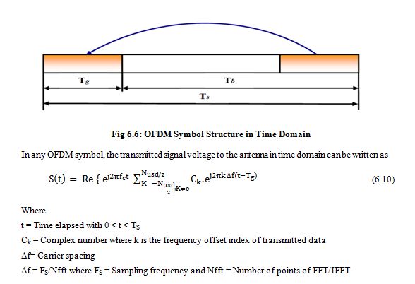
6.3.9 OFDM Symbol Description
In WiMAX Transmitter, IFFT (Inverse Fast Fourier Transform) used to create OFDM waveform with the help of modulated data streams. On the other hand in WiMAX receiver end the FFT used to demodulate the data streams. This time duration is defined to as symbol time, Tb. A copy of symbol period, Tg which is termed of Cyclic Prefix (CP) used to collect multipath where maintaining the orthogonality of the codes. The following fig 6.6 shows the OFDM symbol in the time domain.
In OFDM system, the number of sub-carriers is 256 which is equal to the FFT size. Each OFDM symbol consists of the following four types of carriers .
Data sub-carriers (OFDM) or sub-channels (OFDMA): used for data transmission
Pilot sub-carriers: used for various estimation purposes
DC sub-carriers: used as center frequency
Guard sub-carriers/Guard bands: used for keeping space between OFDM and OFDMA signals
The following fig 6.7 shows the OFDM symbol in frequency domain,
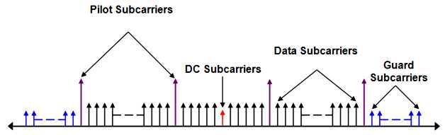
Fig 6.7: OFDM Symbol in frequency domain [28]
To avoid Intersymbol Interference (ISI) the Cyclic Prefix (CP) is inserted in OFDM system before each transmitted symbol. In wireless transmission the transmitted signals might be distort by the effect of echo signals due to presence of multipath delay. The ISI is totally eliminated by the design when the CP length is greater than multipath delay. After performing Inverse Fast Fourier Transform (IFFT) the CP will be add with each OFDM.
6.3.10 CP Insertion
To maintain the frequency orthogonality and reduce the delay due to multipath propagation, cyclic prefix is added in OFDM signals. To do so, before transmitting the signal, it is added at the beginning of the signal. In wireless transmission the transmitted signals might be distort by the effect of echo signals due to presence of multipath delay. The ISI is totally eliminated by the design when the CP length L is greater than multipath delay. After performing Inverse Fast Fourier Transform (IFFT) the CP will be add with each OFDM symbol.
6.4 Channel Module / Wireless Channel
In wireless communication, the data are transmitting through the wireless channel with respective bandwidth to achieve higher data rate and maintain quality of service. The transmitting data has to take environmental challenges when it is on air with against unexpected noise. That’s why data has to encounter various effects like multipath delay spread, fading, path loss, Doppler spread and co-channel interference. These environmental effects play the significant role in WiMAX Technology. To implement an efficient wireless channel have to keep in mind the above fact. In this section we are presenting the wireless channels.
- Additive White Gaussian Noise (AWGN)
- Rayleigh Fading Channel
- Stanford University Interim (SUI)
6.4.1 Additive White Gaussian Noise (AWGN)
This is a noise channel. This channel effects on the transmitted signals when signals passes through the channel. This noise channel model is good for satellite and deep space communication but not in terrestrial communication because of multipath, terrain blocking and interference. AWGN is used to simulate background noise of channel. The mathematical expression as in received signal r(t) = s(t) + n(t) is shown in figure 6.8 which passed through the AWGN channel where s(t) is transmitted signal and n(t) is background noise.
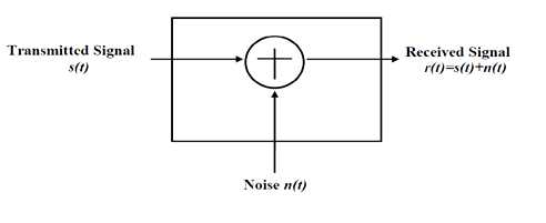
Fig 6.8: AWGN Channel
6.4.2 Rayleigh Fading Channel
Rayleigh Fading is one kind of statistical model which propagates the environment of radio signal. According to Rayleigh distribution magnitude of a signal which has passed though the communication channel and varies randomly. Rayleigh Fading works as a reasonable model when many objects in environment which scatter radio signal before arriving of receiver. When there is no propagation dominant during line of sight between transmitter and receiver on that time Rayleigh Fading is most applicable. On the other hand Rician Fading is more applicable than Rayleigh Fading when there is dominant line of sight. During our simulation we used Rayleigh Fading when we simulate the performance of Bit Error Rate Vs Signal to Noise Ratio.
6.5 Receiver Module
Omni directional Antenna is the most popular antenna in WiMAX, which can be used for point-to-multipoint configuration. The main feature of Omni Directional antenna is that, it can be deployed broad-casting in 3600 angle. This is the limitation of its range and ultimately it shows its signed strength. Omni directional antennas are mostly user friendly when lots of subscribers stay very close to the base station.
6.5.1 CP Removal
In transmitting module, to deal the frequency orthogonality and reduce the delay, cyclic prefix added in each OFDM signals. That’s why, before transmitting the signal, the CP added at the beginning of the signal. After performing Inverse Fast Fourier Transform (IFFT) the CP will be add with each OFDM symbol. In receiver module, after synchronization the received data contains the Cyclic Prefix of each OFDM signal which is ignored.
6.5.2 FFT
By using number of samples FFT converts time domain signal into frequency domain signal. The FFT frequency domain signal defined as 1/ Ts_tot (where Ts_tot is total number of samples). In transmitter module, IFFT converts the OFDM signals from frequency domain to time domain which is exactly reverse work of FFT. To perform of OFDM 256 points, the zeros are padded beginning and ending of the OFDM signal. These zero pads will be removed from the corresponding places at the receiving module.
6.5.3 Channel Equalizer
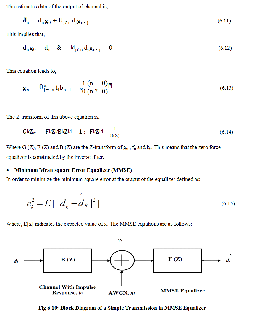
In our simulation we used Zero-Force Bock Equalizer (ZFE) and Minimum Mean Square Equalizer (MMSE) which are described below.
- Zero-Force Block Equalizer (ZFE)
Zero force channel equalizer removes the output of equalizer Inter symbol interference (ISI) from the channel. This equalizer works as a noise remover but if the channel has no noise then it remain ideal condition.
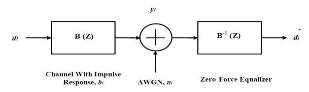
Fig 6.9: Block Diagram of a Simple Transmission in Zero-Force Equalizer
6.5.4 Demodulation
Demodulation works to extract the original data from a modulated waveform. At the receiver, an electronic circuit works to recover the different base-band signals which have already transmitted from the transmitter end which is called demodulator [30].
Chapter 7
Simulation Results
In this chapter the simulation results are shown and discussed. In the following sections, first we will present the structure of the implemented simulator and then we will present the simulation results.
7.1 Bit Error Rate (BER)
When number of bits error occurs within one second in transmitted signal then we called Bit Error Rate (BER). In another sentence Bit Error rate is one type of parameter which used to access the system that can transmit digital signal from one end to other end. We can define BER as follows,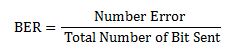
If transmitter and receiver’s medium are good in a particular time and Signal-to-Noise Ratio is high, then Bit Error rate is very low. In our thesis simulation we generated random signal when noise occurs after that we got the value of Bit error rate.
7.2 SNR
Energy per bit to noise power spectral density ratio is important role especially in simulation. Whenever we are simulating and comparing the Bit Error rate (BER) performance of adaptive modulation technique is very necessary Eb/N0. The normalized form of Eb/N0 is Signal-to- Noise Ratio (SNR). In telecommunication, Signal-to-Noise ratio is the form of power ratio between a signal and background noise,
Here P is mean power. In this case the signal and the background noise are measured at the same point of view if the measurement will take across the same impedance then SNR would be obtained by measuring the square of the amplitude ratio.
![]()
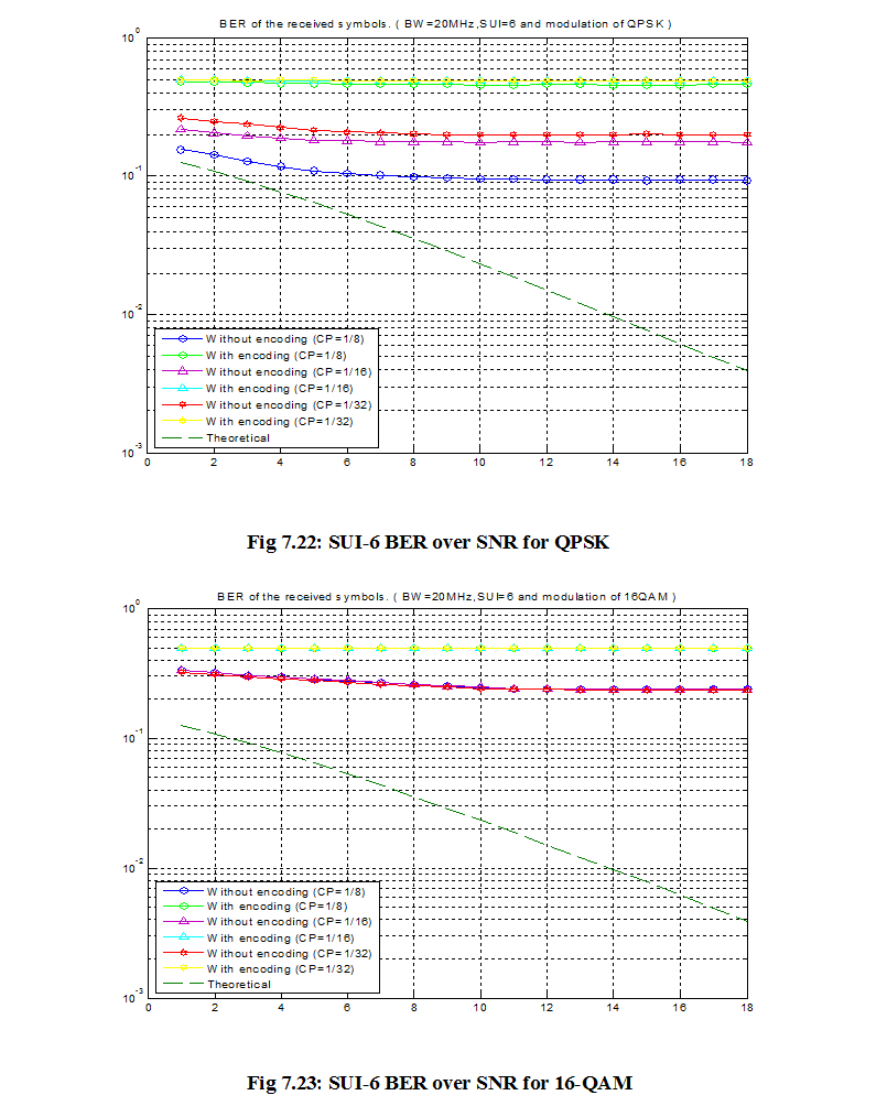
7.3 BER Vs SNR
The Bit Error Rate (BER) defined as the probability of error (Pe). On the other hand Signal-to- Noise is the term of power ratio between a signal and background noise. There are three variables like,
- The error function (erf)
- The energy per bit (Eb)
- The noise power spectral density (N0)
Every modulation scheme has its own value for the error function. That is why each modulation scheme performs in different manner due to the presence of background noise. For instance, the higher modulation scheme (64-QAM) is not robust but it carries higher data rate. On the contrary, the lower modulation scheme (BPSK) is more robust but carries lower data rate. The energy per bit, Eb defined by dividing the carrier power and measured of energy with the unit of Joules. Noise power spectral density (N0) is power per hertz with the unit of Joules per second. So, it is clear that the dimension of SNR is cancelled out. So we can agree on that point that, the probability of error is proportional to Eb/N0.
7.4 Physical layer performance results
The basic goal of this thesis is to analyze the performance of WiMAX OFDM physical layer based on the simulation results. In order to analyze, the BER Vs SNR plot was investigated.
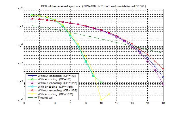
Fig 7.1: SUI-1 BER over SNR for BPSK
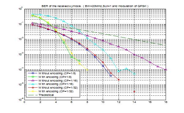
Fig 7.2: SUI-1 BER over SNR for QPSK
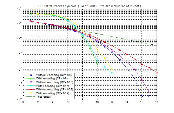
Fig 7.3: SUI-1 BER over SNR for 16-QAM
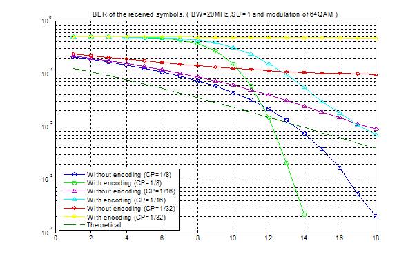
Fig 7.4: SUI-1 BER over SNR for 64-QAM
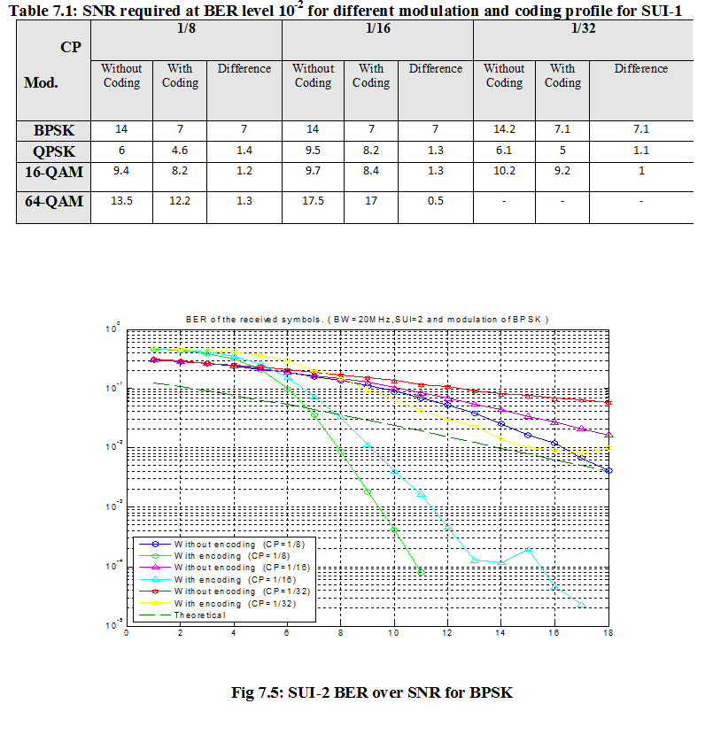
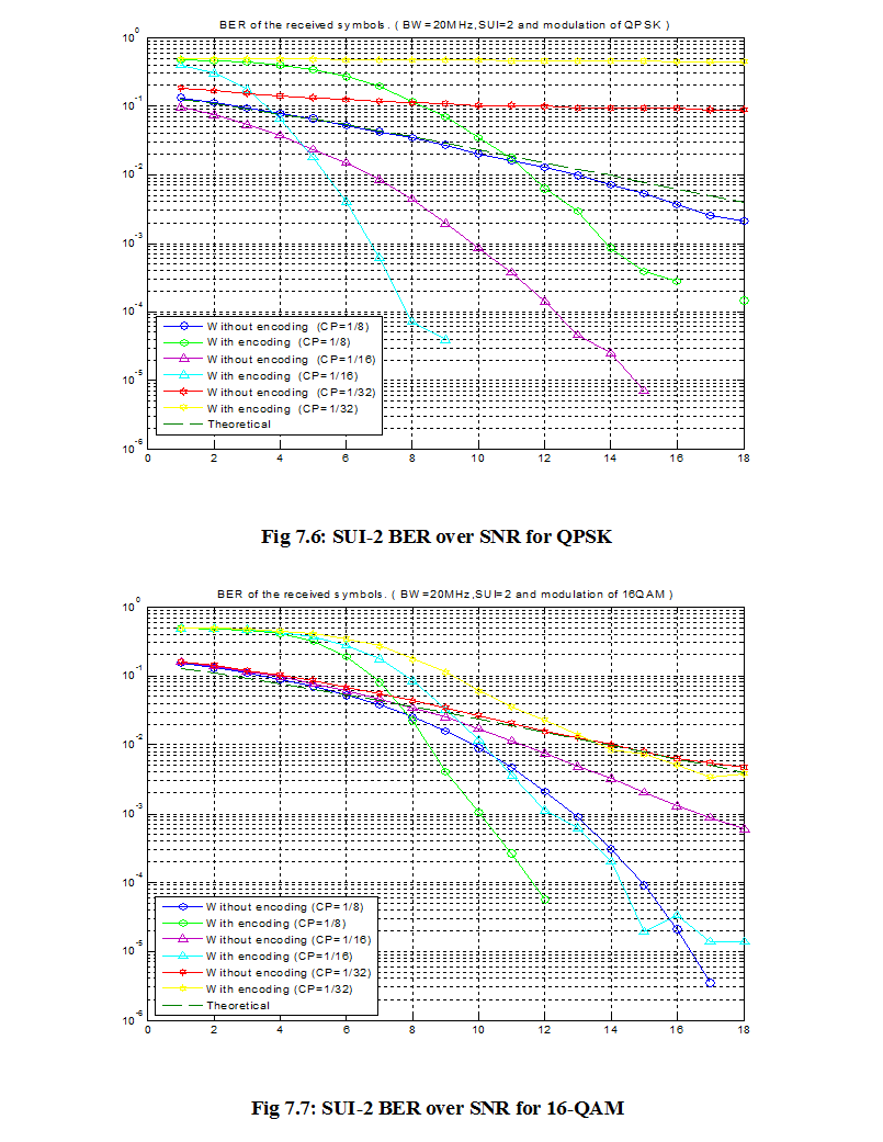
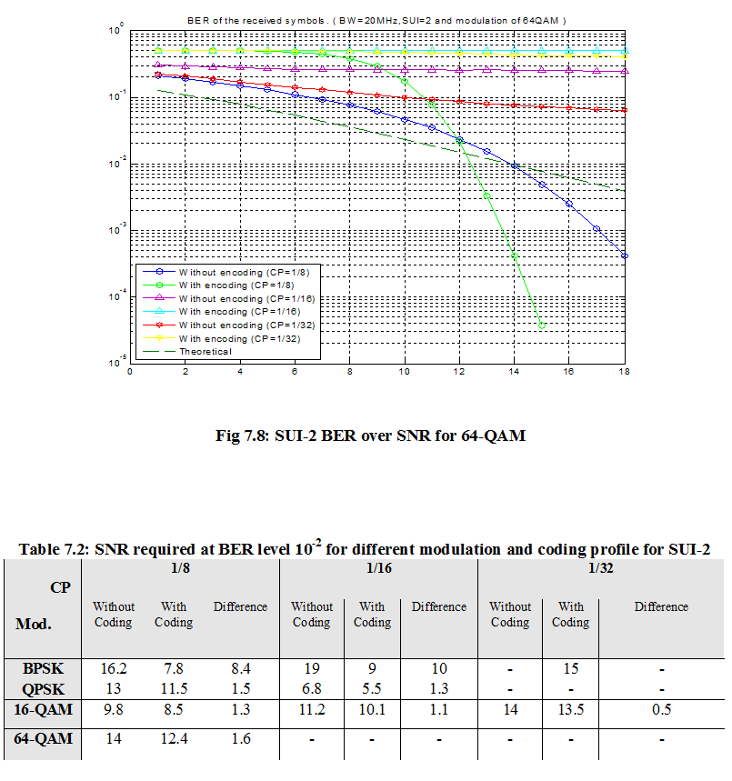
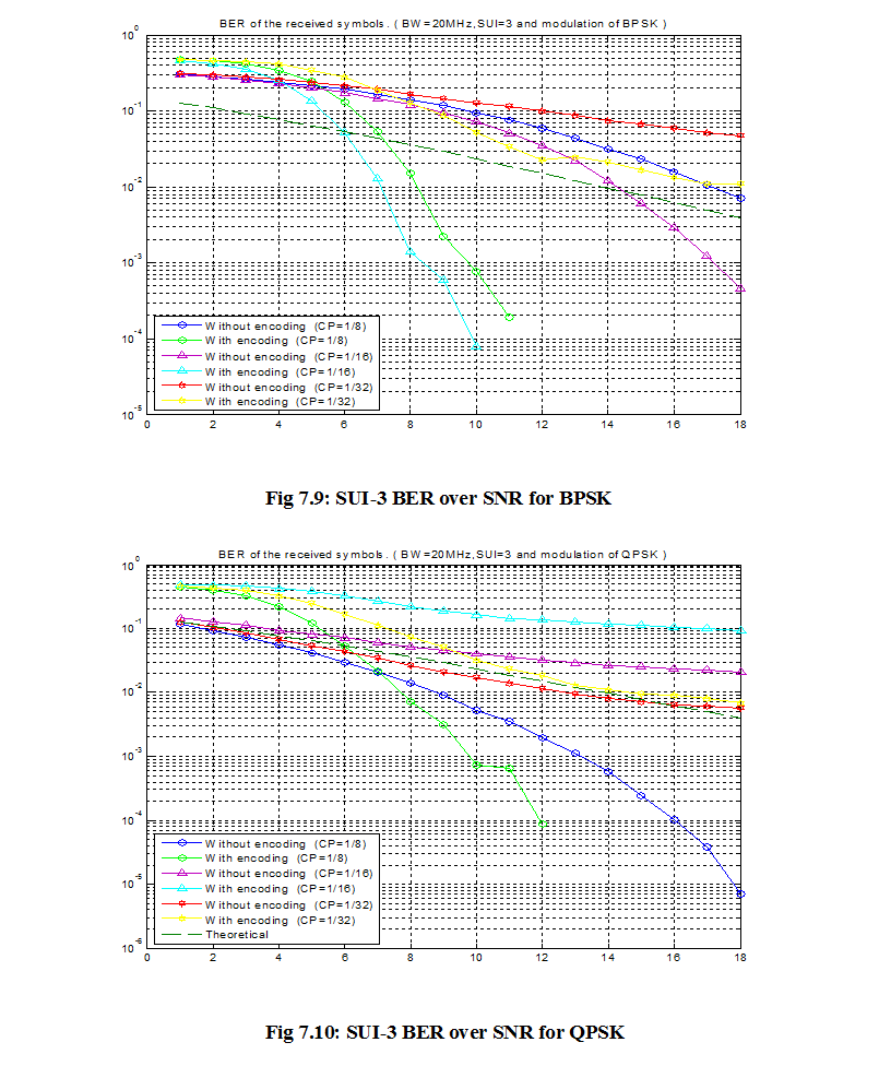
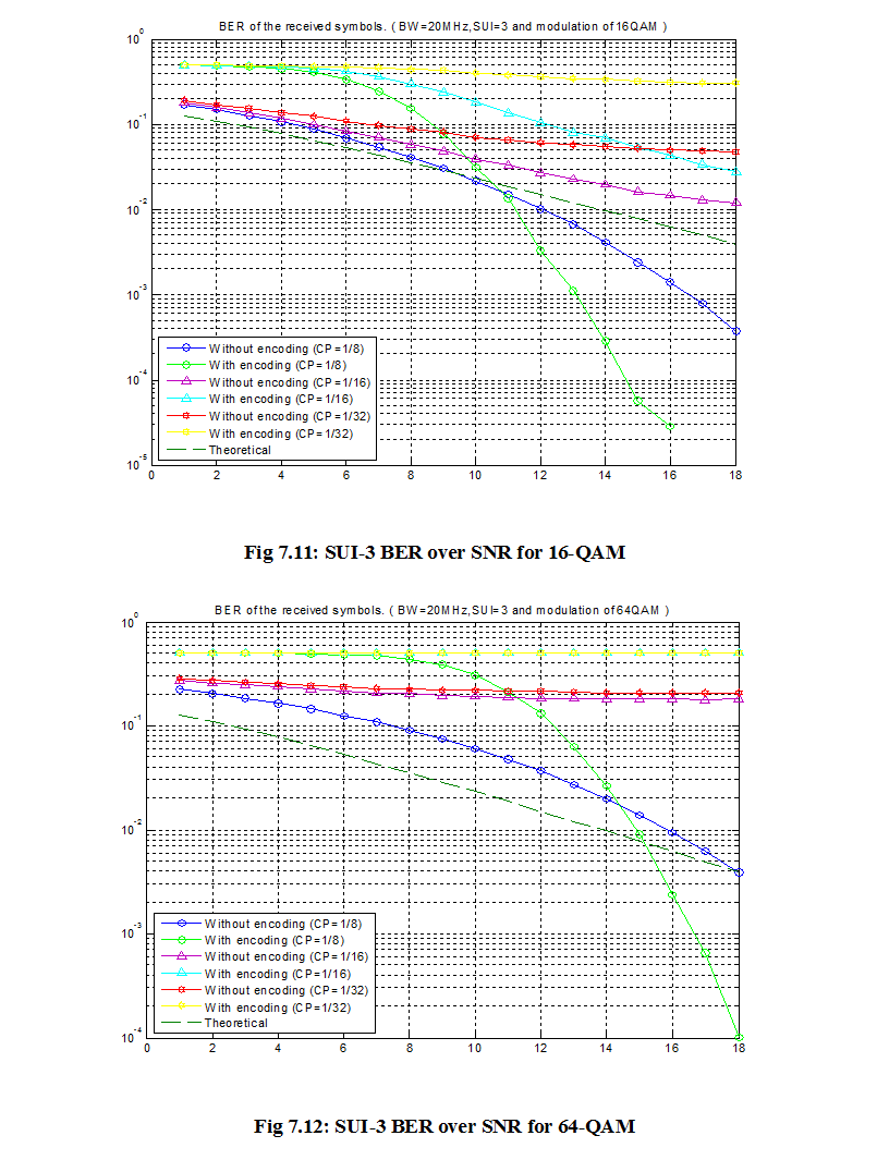
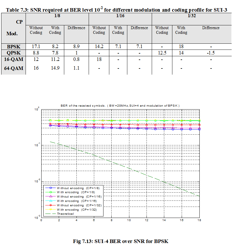
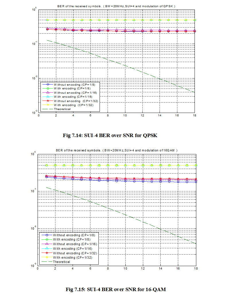

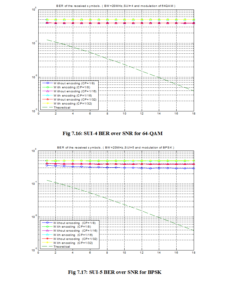
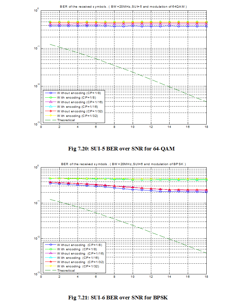
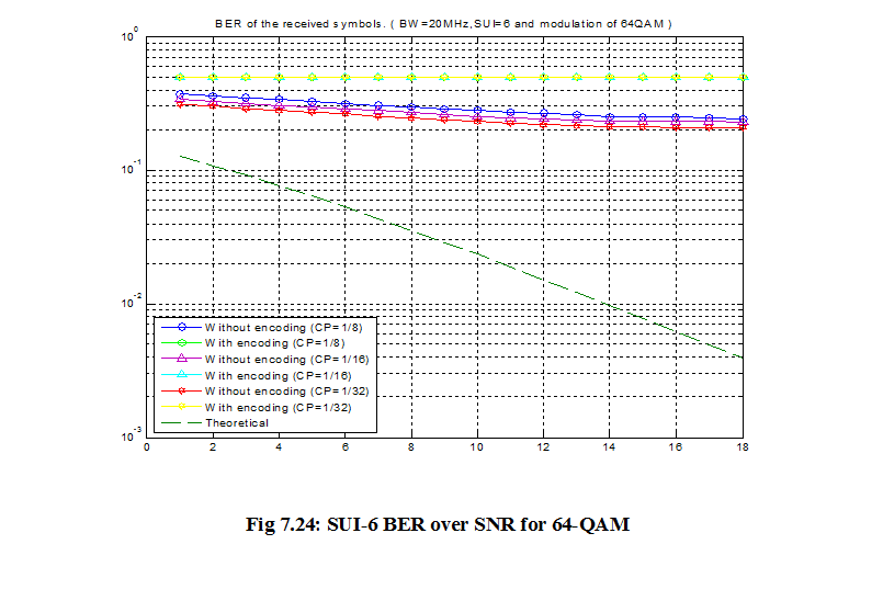
7.5 Conclusion :
After all conditions we applied and the results we got we can conclude our work as follows,
- We studied WiMAX OFDM physical layer, mobile systems, modulation techniques and features of WiMAX networks properly, with the help of necessary figures and tables.
- We studied SUI-1 to SUI-6 channel model and also implemented it through Matlab simulation to evaluate the performance of Mobile WiMAX.
- We also used and understood the adaptive modulation techniques like, BPSK, QPSK, 16-QAM and 64-QAM according to IEEE 802.16d standard.
In all aspects of adaptive modulation technique, we can conclude the performance of Mobile WiMAX as,
- Binary Phase Shift Keying (BPSK) is more power efficient and needs less bandwidth.
- On the other hand 64-Qadrature Amplitude Modulation (64-QAM) has higher bandwidth with very good output.
- In another case, Quadrature Phase Shift Keying (QPSK) and 16-QAM modulation techniques are in middle of those two (BPSK and 64-QAM) and they requires higher bandwidth.
- QPSK and 16-QAM are less power efficient than BPSK.
- During all simulations we got, BPSK has the lowest BER and 64-QAM has the highest BER than other modulation techniques.
We also add some more things in here,
- We included Cyclic Prefix (CP) and random signals which reduced noise resulting lower Bit error Rate (BER) for OFDM system but increased the complexity in the system.
- Cyclic Prefix requires higher power but non Cyclic Prefix requires lower power.
7.6 Future Work:
A lot of works can be done for future optimization of Wireless communication especially in WiMAX system. Adaptive modulation techniques and WiMAX physical layer can be adopted with High Amplitude Platform (HAP) and Long Term Evaluation (LTE).
The implemented PHY layer model still needs some improvement. The channel estimator can be implemented to obtain a depiction of the channel state to combat the effects of the channel using an equalizer. The IEEE 802.16 standard comes with many optional PHY layer features, which can be implemented to further improve the performance. The optional Block Turbo Coding (BTC) can be implemented to enhance the performance of FEC. Space Time Block Code (STBC) can be employed in DL to provide transmit diversity.
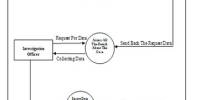
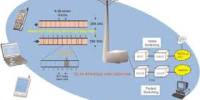
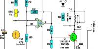
![Report on Models for Nanometer Size MESFETs [ Part-2 ]](https://assignmentpoint.com/wp-content/uploads/2013/04/MESFET-200x100.jpg)