Introduction
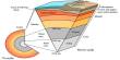
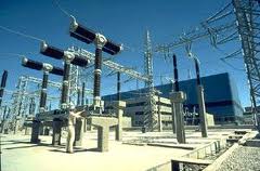
A substation is a component of an electricity transmission or distribution system where voltage is transformed from high to low, or the reverse, using transformers. A transmission substation transforms the voltage to a level suitable for transporting electric power over long distances. This is to minimize capital and operating costs of the system. Once it is transported close to where it Is needed, a distribution substation transforms the voltage to a level suitable for the distribution system. So the assembly of apparatus used to change some characteristic of electric supply is called a substation In a substation using step up and step down transformer change AC voltages from one level to
Another, change AC to DC or DC to AC. A substation may have one or more relates transformers, many protective equipment and switches.
Substation is important part of power transmission and distribution system. Substations are the most critical part of any electrical supply grid. A failure of a single piece of substation equipment
can cause a total grid collapse which may take days or even longer to rectify. The continuity of power supply depends on successful operation of substations. It is therefore essential to exercise
Extreme care while designing and building a substation. Specific functions of substation are-
Power transformer.
Local network for Connection point.
Switchyard – Bus bars, circuit breakers, disconnections.
Measuring point for control center – Potential and current transformers.
Fuses and other protection device.
Classification of substations:
There are the two most important ways of classifying a substation. According to
1. Production requirement
2. Constructional features
According to Production requirement:
A substation may be called upon to change voltage level or improve power factor or convert ac power into dc power etc. According to service requirement 11kV substation is
Transformer substation. In this substations using power transformer changes voltage level of electric supply.
According to constructional features:
A substation has many components (e.g. Circuit breaker, switches, fuses, instrument etc.) Which must be housed properly to ensure continuous and reliable service. According to constructional features the substation is outdoor type Substation.
The outdoor equipment is installed under the sky. Outdoor type substations should be in fenced enclosures or located in special-purpose buildings. Indoor substations are usually found in urban
areas to reduce the noise from the transformers, for reasons of appearance, or to protect switchgear from extreme climate or pollution conditions .
11/.440 kV Substation Arrangement
The arrangement of substations can be done in many ways. However the main sectors of arranging the substations are –
At load center: Where voltage is getting down 11kV to 400volts using transformer and this is near to be load center.
Substation Layout
a) Principle of Substation Layouts
Substation layout consists essentially in arranging a number of switch gear components in an ordered pattern governed by their function and rules of spatial separation.
b) Spatial Separation
i. Earth Clearance: This is the clearance between live parts and earthed structures, walls, screens and ground.
ii. Phase Clearance: This is the clearance between live parts of different phases.
iii. Isolating Distance: This is the clearance between the terminals of an isolator and the connections.
iv. Section Clearance: This is the clearance between live parts and the terminals of a work section. The limits of this work section, or maintenance zone, may be the ground or a platform from which the man works
c) Separation of maintenance zones
Two methods are available for separating equipment in a maintenance zone that has been isolated and made dead.
i. The provision of a section clearance
ii. Use of an intervening earthed barrier
The choice between the two methods depends on the voltage and whether horizontal or vertical clearances are involved.
Equipment Function
Bus-bar
The incoming and outgoing lines are connected to the bus- bars.
- Isolator Disconnect a part of the system for general maintenance and repair under no load condition for safety.
- Earthling Switch
- Discharge the over voltage to earth.
- Circuit Breaker Which can automatic open or close a circuit under normal as well as fault condition.
- Lightning Arrestor discharge lightning over voltages and switching over voltages to earth.
- Current Transformer
- Step down current to know the ratio for control and protection. Voltage Transformer Step down voltage to know the ratio for control and protection.
- Series Reactors
- Reduce the short circuit current or starting current.
- Line Trap Prevent high frequency signals during low loads.
- Shunt capacitors Provide compensation to reactive loads of lagging power
- Factors.
- Shunt Reactor in EHV
- substations
- To provide reactive power during low loads.
- Neutral Grounding Resistor Limit the earth current.
Functions of a Substation
1 – Supply of required electrical power.
2 – Maximum possible coverage o f the supply network.
3 – Maximum security of supply.
4 – Shortest possible fault-duration.
5 – Optimum efficiency of plants and the network.
6 – Supply of electrical power within targeted frequency limits (49.5 Hz and50.5 Hz).
7 – Supply of electrical power within specified voltage limits.
8 – Supply of electrical energy to the consumers at the lowest cost.
Elements of a Substation
Substations have one or more transformers, switching and control equipment. In a substation, circuits breakers are used to interrupt any short-circuit or overload currents that may occur on the
network. Substations do not usually have generators, although a power plant may have a
substation nearby. Other devices such as power factor correction capacitors, synchronizer and voltage regulators may also be located at a substation. The main equipments of a substation are shown –
11/.440 kV Substation equipments details
Transmission line set giving the rated voltage level up to 11 kV. This 11 kV lines are connected to the 7MVA transformer via 33 kV bus bars is further connected to LT switchgear.
The equipment required for a transformer Sub- Station depends upon the type of Sub-Station, Service requirement and the degree of protection desired. 11kV Sub-Station has the following major equipments.
Transformer:
7MVA 33/11Kv Main Transformer,
4 MVA.3 MVA.2 MVA.&1.5 MVA
2. Lightning arrestor
3. Isolator and Earth switches
4. Current Transformer
5. Potential Transformer
6. Duplicate type bus bar
7. Insulators
8. PFI Plant
9. LT Switchgear –5000Amps, 4000Amps,3000Amps,2000Amps.1500Amps.all LT Switch Gear are Various ACB
Faraday’s law of induction, which states that:
The induced electromotive force (EMF) in an y closed circuit is equal to the e time rate of change of the magnetic flux through the circuit. Or alternatively:
The EMF generated is proportional to the rate of change of the magnetic flux.
where Vs is the instantaneous voltage, Ns is the number of turns in the secondary y coil and
equals the magnetic flux through one turn of the coil. If the turns of the coil are oriented perpendicular to the magnetic field lines, the flux is the product of the magnetic flux density B and the area A through which it cuts. The area is constant, being equal to the cross-sectional area
of the transformer core, whereas the magnetic field varies with time according to the excitation of the primary. Since the same magnetic flux passes through both the primary and secondary coils in an ideal transformer, the instantaneous voltage across the primary y winding equals
Electrical power is transmitted from the primary circuit to the secondary circuit. The transformer
is perfectly efficient; all the incoming energy is transformed from the primary cir cuit to the magnetic field and into the secondary circuit. If this condition is met, the incoming electric power must equal the outgoing power.
Transformers normally have high efficiency more then 95%, so this formula is a reasonable approximation. If the voltage is increased, then the current is decreased by the same factor. The
Impedance in one circuit is transformed by the square of th e turn’s ratio.
Transformer E MF equation
If the flux in the core is purely sinusoidal, the relationship for either winding between its rms voltage Erm of the winding , and the supply frequency f, number of turns N, core cross-sectional
area a and peak magnetic flux density B If the flux does not contain even harmonics the following equation can be used for half-cycle
average voltage E
a of any wave shape:
Transformer ratios:
The voltage ratio of a constant-voltage transformer, i.e., the ratio of primary to secondary voltage, depends primarily upon the ratio of the primary to the secondary turns. The voltage ratio will vary slightly with the amount and power factor of the load. For general work the voltage ratio can be taken as equal to the turn ratio of the windings. The current
ratio of a constant-voltage transformer will be approximately equal to the inverse ratio of the turns in the two windings
The regulation of a transformer is the change in secondary voltage from no load to full load. It is generally expressed as a percentage of the full-load secondary voltage.
The regulation depends upon the design of the transformer and the power factor of the lo ad. Although with a non inductive load such as incandescent lamps, the regulation of transformers is
within about 3 percent, with an inductive load the drop in voltage between no load and full load
increases to possibly about 5 percent. If the motor load is large and fluctuating and close lamp regulation is important, it is desirable to use separate transformers for the motors.
The efficiency of a transformer is, as with any other device, the ratio of the output to input or, in other words, the ratio of the output to the output plus the losses. As a formula it can be expressed thus:
The copper loss of a transformer is determined by the resistances of the high-tension and low-
tension windings and of the leads. It is equal to the sum of the watts of I 2R losses in these components at the load for which it is desired to compute the efficiency.
The iron loss of a transformer is equal to the sum of the losses in the iron core. These losses consist of eddy- or Foucault-current losses and hysteretic losses. Eddy-current losses are due to
currents generated by the alternating flux circulating within each lamination composing the core,
and they are minimized by using thin laminations and by insulating adjacent laminations with insulating varnish. Hysteretic losses are due to the power required to reverse the magnetism of the iron core at each alternation and are determined by the amount and the grade of iron used for
the laminations for the core.
Transformer ratings. Transformers are rated at their kilovolt-ampere (kVA) outputs. If the load to be supplied by a transformer is at 100 percent power factor (pf), the kilowatt (kW) output
will be the same as the kilovolt-ampere (kVA) output.If the load has a lesser power facto r, the kW output will be less than the kVA output proportionally as the load power factor is less than
100 percent.
Phase Transformer Connection Construction:
A three phase transformer is constructed by winding three single phase transformers on a single core. These transformers are put into an enclosure which is then filled with dielectric oil. The dielectric oil performs several fun ctions. Since it is a dielectric, a nonconductor of electricity, it provides electrical insulation between the windings and the case. It is also used to help provide cooling and to prevent the formation of moisture, which can d eteriorate the winding insulation.
There are only 4 possible transformer combinations: Delta to Delta – use: industrial applications
Delta to Wye – use : most common for step-up transformer; commercial and industrial
Wye to Delta – use : most common for step-down high voltage Wye to Wye – use : rare, don’t use causes harmonics an d balancing problems.
Characteristics of Distribution Transformer:
1. According to method of cooling
a. Oil-immersed, combination self-cooled and fan -cooled
2. According to insulation between windings a. Windings insulated from each other
b. Autotransformers
3. According to number of phases a. Poly-phase
4. According to method of mounting a. Platform
5. According to purpose
a. Constant-voltage
b. Variable-voltage
6. According to service a. large power
b. Distribution
Bus-bar Arrangement
Bus-bars are the important components in a substation .there are several bus-bar arrangement that can be used in substation .The choice of a particular arrangement depends upon various factors such as voltage, position of substation, degree of reliability, cost etc. These are made up of copper and aluminum to which the terminal of generators, transformers, distribution lines, loads etc is connected. In an electrical power distribution system that conduct electricity within a switchboard, distribution board, substation, or other electrical apparatus. These bus-bar are insulated from each other and also from the earth.
The size of the bulbar is important in determining the maximum amount of current that can be safely carried. Bus bars can have a cross-sectional area o f as little as 10 mm² but electrical substations may use metal tubes of 50 mm in diameter (1,963 mm²) or more as bus bars.
The following are the important bus-bar arrangements used in substation.
• Single busbar
• Single busbar system with sectionalisation
• Double/ Duplicate bus-bar arrangement
Duplicate type busbar
This system consists of two bus-,a main bar-bar and a spare bus-bar. Each bus bar has the capacity to take up the entire substation load .The incoming and outgoing lines can be connected
to either bus-bar with the help of a bus-bar coupler which consists of a circuit breaker and
Isolators. The incoming and outgoing lines remain connected to the main bus bar. However, in case of repair of main bus-bar or fault occurring on it, the continuity of supply to the circuit can
be maintained by transferring it to the spare bus-bar.
Insulators
The insulator serves two purpose. They support the conductor (or bus bar ) and con fine the current to the conductor. The most commonly used material for the manufactures of insulators is porcelain. There are several type of insulator (i.e. pine type, suspension type etc.) and there used in Sub-Station will depend upon the service requirement.
Earth system :
Why ground?
Poor grounding not only contributes to unnecessary downtime, but a lack of good grounding is also dangerous and increases the risk of equipment failure .Without an effective grounding system ,we could be exposed to the risk of electric shock , not to mention instrumentation errors ,harmonic distortion issues, power factor problems and a host of possible intermittent dilemmas.
If fault currents have no path to the ground through a properly designed and maintained grounding system, they will find unintended paths that could include people .The following organizations have recommendations and/or standards for grounding to ensure safety:
• OSHA (Occupational Safety Health Administration)
• NFPA (National Fire Protection Association)
• ANSI/ISA (American National Standards Institute and Instrument Society of America)
• TIA (Telecommunications Industry Association)
• IEC (International Electro-technical Commission)
• CENELEC (European Committee for Electro-technical Standardization)
• IEEE (Institute of Electrical and Electronics Engineers)
However, good grounding isn’t only for safety; it is also used to prevent damage to industrial plants and equipment. A good grounding system will improve the reliability of equipment and reduce the likelihood of damage due to lightning or fault currents .Billions are lost each year in
the workplace due to electrical fires. This does not account for related litigation costs and loss of personal and corporate productivity.
Why test grounding systems?
Over time, corrosive soils with high moisture content, high salt content, and high temperatures can degrade ground rods and their connections. So although the ground system when initially installed, had low earth ground resistance values, the resistance of the grounding system can increase if the ground rods are eaten away. With frustrating, intermittent electrical problems, the problem could be related to poor grounding or poor power quality .That is why it is highly recommended that all grounds and ground connections are checked at least annually as a part of
your normal Predictive Maintenance plan. During these periodic checks, if an increase in resistance of more than 20 % is measured, the technician should investigate the source of the problem, and make the correction to lower the resistance, by replacing or adding ground rods to
the ground system.
What is a ground and what does it do?
The NEC, National Electrical Code, Article 100 defines a ground as: “a conducting connection, whether intentional or accidental between an electrical circuit or equipment and the earth, or to some conducting body that serves in place of the earth.” When talking about grounding, it is actually two different subjects: earth grounding and equipment grounding. Earth grounding is an intentional connection from a circuit conductor, usually the neutral, to a ground electrode placed in the earth. Equipment grounding ensures that operating equipment within a structure is
properly grounded. These two grounding systems are required to be kept separate except for a connection between the two systems. This prevents differences in voltage potential from a
possible flashover from lightning strikes. The purpose of a ground besides the protection of people, plants and equipment is to provide a safe path for the dissipation of fault currents, lightning strikes, static discharges, EMI and RFI signals and interference.
What is a good ground resistance value?
There is a good deal of confusion as to what constitutes a good ground and what the ground resistance value needs to be. Ideally a ground should be of zero ohms resistance .There is not one
Standard ground resistance threshold that is recognized by all agencies. However, the NFPA and IEEE have recommended a ground resistance value of 5.0 ohms or less. The NEC has stated to “Make sure that system impedance to ground is less than 25 ohms specified in NEC 250.56. In facilities with sensitive equipment it should be 5.0 ohms or less.” The Telecommunications industry has often used 5.0 ohms or less as their value for grounding and bonding .The goal in ground resistance is to achieve the lowest ground resistance value possible that makes sense economically and physically.
Components of a ground electrode
• Ground conductor
• Connection between the ground conductor and the ground electrode
• Ground electrode
Locations of resistances
(a)The ground electrode and its connection
The resistance of the ground electrode and its connection is generally very low. Ground rods are generally made of highly conductive/low resistance material such as steel or copper.
(b) The contact resistance of the surrounding earth to the electrode
The National Institute of Standards (a governmental agency within the US Dept. of Commerce)has shown this resistance to be almost negligible provided that the ground electrode is free of paint, grease, etc. and that the ground electrode is in firm contact with the earth.
(c) The resistance of the surrounding body of earthThe ground electrode is surrounded by earth which conceptually is made up of concentric shells all having the same thickness. Those shells closest to the ground electrode have the smallest amount of area resulting in the greatest degree of resistance. Each subsequent shell incorporates
a greater area resulting in lower resistance. This fin ally reaches a point where the additional shells offer little resistance to the ground surrounding the ground electrode. So based on this information, we should focus on ways to reduce the ground resistance when installing grounding systems.
What affects the grounding resistance?
First, the NEC code (1987, 250-83-3) requires a minimum ground electrode length of 2.5 meters (8.0 feet) to be in contact with soil. But, there are four variables that affect the ground resistance of a ground system:
1. Length/depth of the ground electrode
2. Diameter of the ground electrode
3. Number of ground electrodes
4. Ground system design
Length/depth of the ground electrode
One very effective way of lowering ground resistance is to drive ground electrodes deeper. Soil is not consistent in its resistivity and can be highly unpredictable. It is critical when installing the ground electrode, that it is below the frost line. This is done so that the resistance to ground will not be greatly influenced by the freezing of the surrounding soil. Generally, by doubling the length of the ground electrode you can reduce the resistance level by an addition a l0 %. There are occasions where it is physically impossible to drive ground rods deeper—areas that are composed of rock, granite, etc. In these instances, alternative methods including grounding cement are viable.
Diameter of the ground electrode
Increasing the diameter of the ground electrode has very little effect in lowering the resistance. For ex ample, you could double the diameter of a ground electrode and your resistance would only decrease by 10 %.
Number of ground electrodes
Figure -: Each ground electrode has its own ‘sphere of influence’.
Another way to lower ground resistance is to use multiple ground electrod es. In this design, more than one electrode is driven into the ground and connected in parallel to lower the resistance. For additional electrodes to be effective, the spacing of additional rods need to be at least equal to the depth of the driven rod. Without proper spacing of the ground electro des, their spheres of influence will intersect and the resistance will not be lowered. To assist you in installing a g that will meet your specific resistance requirements, you can use the table of ground resistances, below. Remember, this is to only be used as a rule of thumb, because soil is in layers and is rarely homogenous. The resistance values will vary greatly.
Ground system design
Simple grounding systems consist of a single ground electrode driven into the ground. The use of a single ground electrode is the most common form of grounding and can be found outside your home or place of business. Complex grounding systems consist of multiple ground rods, connected, mesh or grid networks, ground plates, and ground loops. These systems are typically installed at power generating substations, central offices, and cell tower sites. Complex networks dramatically increase the amount of contact with the surrounding earth and lower ground resistances.
Figure: – Mesh network, Ground plate.
How do I measure soil resistance?
To test soil resistivity, connect the ground tester as shown below. As you can see, four earth ground stakes are positioned in the soil in a straight line, equidistant from one another. The distance between earth ground stakes should be at least three times greater than the stake depth. So if the depth of each ground stake is one foot (.30meters), make sure the distance between stakes is greater than three feet (.91 meters). The Fluke 1625 generates a known current through the two outer ground stakes and the drop in voltage potential is measured between the two inner
Ground stakes. Using Ohm’s Law (V=IR), the Fluke tester automatically calculates the soil resistance. Because measurement results are often distorter and invalidated by underground pieces of metal, underground aquifers, etc. additional measurements where the stake’s axis are turned 90 degrees is always recommended. By changing the depth and distance several times, a profile is produced that can determine a suitable ground resistance system. Soil resistivity measurements are often corrupted by the existence of ground currents and their harmonics. To prevent this from occurring, the Fluke 1625 uses an Automatic Frequency Control (AFC) System. This automatically selects the testing frequency with the least amount of noise enabling you to get a clear reading.
What are the Methods of Earth Ground Testing?
Fall-of-Potential measurement
The Fall-of-Potential test method is used to measure the ability of an earth ground system or an individual electrode to dissipate energy from a site.
How does the Fall-of-Potential test work?
First, the earth electrode of interest must be disconnected from its connection to the site. Second, the tester is connected to the earth electrode. Then, for the 3-pole Fall-of-Potential test, two earth stakes are placed in the soil in a direct line—away from the earth electrode. Normally,
spacing of 20 meters (65 feet) is sufficient. For more detail on placing the stakes, seethe next section. A known current is generated by the Fluk e 1625 between the outer stake (auxiliary earth stake) and the earth electrode, while the drop in
Voltage potential is measured between thee earth stake and the earth electrode. Using Ohm’s Law
(V = IR ), the tester automatically calculates the resistance of the earth electrode. Connect the ground tester as shown in the picture. Press START and read out the RE (resistance) value. This is the actual value of the ground electrode under test. If this ground electrode is in parallel or series with other ground rods, the RE value is the total value of all resistances.
How do you place the stakes?
To achieve the highest degree of accuracy when performing a 3–pole ground resistance test, it is essential that the probe is placed outside the sphere of influence of the ground electrode under test and the auxiliary earth. If you do not get outside the sphere of influence, the effective areas
of resistance will overlap and invalidate an y measurements that you are taking. The table is a guide for appropriately setting the probe (inner stake) and auxiliary ground (outer stake).To test the accuracy of the results and to ensure that the ground stakes are outside the spheres of influence, reposition the inner stake(probe) 1 meter (3 feet) in either direction and take a fresh measurement. If there is a significant change in the reading (30 %), you need to increase the distance between the ground rod under test, the inner stake (probe) and the outer stake (auxiliaryground) until the measured values remain fairly constant when repositioning the inner stake.
Specification
11/0.415kV, 7MVA Sub-station of Instrument is …
a) 7MVA 33/11Kv Main Transformer,4 MVA.3 MVA.2 MVA.&1.5 MVA kVA Transformer 11kV/0.415kV
b) LT Switchgear-5000A 4000A 3000A
c) Dropout Fuse, Rated Voltage (Nominal) -11kV, Rated Current RMS -100A,1Set
d) Lightning Arrester , Rated Voltage (RMS) – 9kV, 1Set
e) 7Mva – 3 Units1500 KVAR-tow units,150KVAR 5-Units Automatic PFI Plant.
f) Current Transformer, Ratio 2500/5A 1000/5A-500/5A,
g) Potential Transformer, Ratio -11//110V , 3pcs.
Setup Information
Factory requirement following as there instrument will be ascension. There Instrument of the figure same as connection from the distribution line. I always help them to connection and working time.
First time we are connected Isolator. It connect to main line include drop out Fuse 15A, nos. of
3pcs, for 3 phase. Isolator one terminals connect to main distribution line (11kv line) another terminals connect to current transformer of primary side. This Isolator attach on the front of poll. After transformer connection. Transformer connected is delta to star, primary side is delta and secondary side is star. primary side voltage is 11kV and secondary voltage is 420V. Secondary side of common terminal connected to grounding and also transformer body connected to grounding. Primary side bushing number is 3pcs. and secondary side bushing number is
4pcs.Transfomer all of check, oil level, silica gel, temperature, and all nut bolt. Transformer secondary side connect to LT switch gear (Low tension) its medium is LT cable.
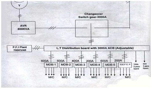
Now Low tension switch gear connection. Low tension indoor type switchgear with hard drawn copper bus-bars, TPN&E equipped with incoming connected is 1no. 500A, 36kA, TP MCCB with adjustable thermal overload and adjustable magnetic short-circuit releases. 3nos. current transformer, ratio:500/5A with suitable accuracy and burden. 3nos. Ammeter, 0-500A.
1no.Voltmeter, 0-500V with selector switch. 2nos. indicating lamp on/off and 1 set control fuse.
Out going is 1no. 250A,36kA,TP MCCB with adjustable thermal overload and adjustable magnetic short circuit releases. 3nos. 100A, 16kA, TP MCCB with adjustable thermal overload and adjustable magnetic short circuit releases. 2nos. 160A, 16kA, TP MCCB with adjustable thermal overload and adjustable magnetic short circuit releases. Low tension switch gear by the distributed to factory machineries. And power factor improvement plant connected from low tension switchgear.
Sub-station last pert is 150kVAR automatic power factor improvement plant connected. It is flour mounting, 415V, 50HZ, 150kVAR indoor type Automatic power factor improvement plant,
comprising: 1no. 12.5kVAR bank of TP dry type power capacitor with built-in discharge resistor
(Direct). 1no. 12.5kVAR bank of TP dry type power capacitor with built-in discharge resistor.
3nos. 25kVAR bank of TP dry type power capacitor with built-in discharge resistor. 1no.
50kVAR bank of TP dry type power capacitor with built-in discharge resistor.1no. automatic power factor correction relay. 5 nos. TP air contractors of adequate rating. 18 nos. HRC fuses with base of adequate rating. 5 nos. indicating lamps and 1 set control fuses. And other give the connected on Distribution Box, Switching bo ard etc. There are connected from low tension switchgear. Distribution Box to connect the Machineries line. And all Instrument & machineries of body connected to earth grounding.
Operation of Sub-station:
At many places in the line of the power system, it may be desirable and necessary to change some characteristic (v oltage, frequency, power factor etc.) of electric supply. this is
accomplished by suitable apparatus called sub-station. The sub-station operation explained as under:
1) The 3-phase, 3-wire 11kV line is tapped and brought to th e gang operating switch installed near the sub-station. The G.O. switch consists of isolators connected in each phase of the 3-phase line.
2) From the G.O. switch, the 11kV line is brought to the indoor sub-station as underground cable. It is fed to the H.T. side of the transformer (11kV/400V) via the 11kV O.C.B. The transformer steps down the voltage to 400V, 3- phase, 4 wire.
3) The secondary of transformer supplies to the bus-bars via the main O.C.B. From the bus- bars,400V, 3 phase, 4-wire supply is given to the various consumers via 400V O.C.B. The voltage between any phase and neutral it is 230V. The single phase residential load is
connected between any one phase and neutral whereas 3-phase, 400V motor load is connected across 3 -phase lines directly.
4) The CTs are located at suitable place in the sub-station circuit and supply for the metering and indicating instruments and relay circuits.
Maintenance and Trouble shutting
1 Symmetrical Fault The symmetrical fault rarely The symmetrical fault is the occurs in practice as most severe and imposes more majority of the fault are of heavy duty on the circuit unsymmetrical nature breaker.
The reader to understand the problems that short circuit conditions present to the power system.
2 Single line to ground Any line with short to the Separate to the line from short fault.ground fault.circuit to solve the problem.
Insulation problem.
3 Line to line fault. One line with another line toSeparate to the line from short short.circuit for solving the problem.Insulation problem.
4 Double line to ground Two line with short to the Separate to the line from short fault.
Insulation problem.
problem.
5 Arc phenomenon When a short-short circuit Arc resistance is made to occurs, a heavy current increase with time so that flows the contacts of the current is reduced to a value circuit breaker. Insufficient to maintain the arc.
The ionized particles between the contacts tend to maintain the arc.
6 Transformer open circuit An open circuit in one phase Open phase connect with to fault. of a 3-phase transformer circuit may cause undesirable heating.
Relay protection is not provided against open circuits
On the occurrence of such a because this condition is fault, the transformer can be relatively harmless. disconnected manually from the system.
7 Transformer overheating Over heating of The relay protection is also fault.transformer is usually not provide against this caused by sustained contingency and thermal overloads or short-circuit accessories are generally used and very occasionally by the to sound an alarm or control failure of the cooling the bank of fans.
system.
8 Transformer Winding short-circuit (also The transformer must be short circuit fault. called internal faults) on the disconnected quickly from the
transformer arise from system because a prolonged deterioration of winding arc in the transformer may insulation due to cause oil fire.
overheating or mechanical injury.
9 Lightning for over voltage The surges due to internal Surges due to internal causes fault. causes hardly increase the are taken care of by providing
system voltage to twice the proper insulation to the normal value. equipment in the power system.
A lightning arrester is a protective device which conducts the high voltage surges on the power system to the ground.
10 Low voltage Supply voltage is low. Transformer tap changing turn to move after solved the problem.
SWITCHGEAR
The term switchgear, used in association with the electric power system, or grid, refers to the electrical equipments like isolators, fuses, circuit breakers which intended to connect and disconnect power circuits are known collectively as switchgear. Switchgear is used in connect with generation, transmission, distribution and conversion of electric power for controlling, metering protecting and regulating devices. A basic function of switchgear power systems is protection of short circuits and overload fault currents while simultaneously providing service continuously to unaffected circuits while avoiding the creation of an electrical hazard. Switchgear power systems also provide important isolation of various circuits from different
power supplies for safety issues. There are many different types and classifications of switchgear power systems to meet a variety of different needs.Switchgear power systems can vary, depending on several factors, such as power need, location of system and necessary security. Therefore, there are several different types of switchgear
power systems and each has their own unique characteristics to meet the specific needs of the system and its location.
Switchgear instruments of Factory
Factory has low voltage (up to 380 volt) and medium voltages (up to 400V) switch gear. It is indoor type and switch gear instruments are:
1) Circuit breaker – Miniature circuit breaker, Vacuum circuit breaker, molded case circuit breaker.
2) Relay – Distance Relay, Over current and Earth fault relay, Under/Over voltage relay, Trip circuit supervision relay, Differential protection relay, Static relay
3) Current transformer (C T)
4) Potential transformer (PT)
5) Fuse
6) Lightning arrestor
7) Isolator and Earth switches
8) Magnetic conductor
Current transformers (CT):
Current Transformers are used in current circuits in protection systems employing secondary relays. This transformer is to measure large currents and differs in phase from it by an angle which is approximately zero for an appropriate direction of the connections. This highlights the accuracy requirement of the current transformer but also important is the isolating function. The
primary which is usually of few turns or even a single turn or thick copper or brass bar is inserted into the core of the transformer is connected in series with the load. The secondary current is normally rated for 5A or 1A and the number of turns in the secondary will be high. When the current transformer has two secondary windings then one winding is connected to the protective
relay system and the other is to indicating / metering circuit. Current transformer windings are polar in nature. The current transformers with 1A rating secondary can handle 25 times more burden than the current transformers of 5A secondary. Current Transformers of 1ASecondaries are normally used in the protection of 11 kV – 132 kV.
Transmission lines where the substation apparatus is located at a considerable distance from the control room, where the relays are situated. The magnitude of the current which flows through the secondary winding of a CT is a function of the primary current, the transformation ratio and
also the impedance of the secondary circuit. CT’s normally operate under Conditions close to short circuit conditions. The Secondar y winding burden further depends upon the method of connection of the C T secondary, the relay windings and the kind of short circuit experienced. CT’s used for extra high voltage net work protection must be capable of accurately transmitting currents both during steady state process and under transient conditions in order to permit operation of the protective devices correctly. The reasons for choosing proper CT’s for extra high voltage net work protection are;
1. The time constants of DC components in the short circuit currents of EHV net works are large.
2. The ratio of the short circuit current to the rated current is very high, due to increased energy concentration.
3. High Speed relaying is essential to protect electrical equipment during fault and to increase system stability
The accuracy of a CT is directly related to a number of factors including:
Burden
Burden class/saturation class
Rating factor
Load
External electromagnetic fields
Temperature and
Physical configuration.
The selected tap, for multi-ratio CT’s
Ratio 5000/5A
Potential Transformers (PT):
Instrument Transformers are of means of extending the ran ge of AC in str umen ts like ammeters, voltmeters, V.A.R. meters, Walt-meters. They are two types of potential transformers. The primary of the potential transformers is connected across the transmission line whose voltage may range from 2.4 kV to 220 kV. The secondary voltage is standardized at 110 kV. The load connected to the secondary is referred to as burden. The requirements of the good potential transformers are:
Accurate turns ratio , n = V p/ Vs
The difficulty in maintaining the accurate turn’s ratio is due to resistance and reactance of the windings and the value of the exciting current of the transformer.
Small leakage reactance. The leakage reactance is due to the leakage of the magnetic fluxes of the primary and secondary voltages. They can be minimized by keeping the primary, secondary windings as close as possible subject to insulation problem as the primary is at high voltage.
Small magnetic current. This can be achieved by making the reluctance of the core as small as possible and flux density in the core is also lowland it is very less than 1 wb / m Minimum Voltage Drop: The resistance of the windings is made as small as possible The Primary as it carries high voltage should be heavily insulated. Hence it is immersed in oil and the terminals are brought out to porcelain bushing. Now-a-days synthetic rubber insulation like styrene is used avoiding oil and porcelain. When the load or burden on the secondary is increased, the secondary current increases with corresponding increase in primary current so that transformation ratio remains the same
Specification of Potential Transformer
• Manufacturer : ABB
• Device maximum operating voltage : 35kV
• Rated frequency : 50-60Hz
• Rated voltage : 11 kV
• Rated output : 440V
Lightning Arrestor
A lightning arrester is a device used on electrical power systems to protect the insulation on the system from the damaging effect of lightning. Metal oxide varistors (MOVs) have been used for power system protection since the mid 1970s. The typical lightning arrester also known as surge
arrester has a high voltage terminal and a ground terminal. When a lightning surge or switching surge travels down the power system to the arrester, the current from the surge is diverted around
the protected insulation in most cases to earth.
Specification of Lightning Arrestor
• Manufacturer : ABB
• Rated voltage : 11kV
• Rated current : 50-60Hz
• Rated discharging current : 10kA
• Continuous operating voltage : 100.8kV
• Residual voltage under thunder In : 10kA 615kV peak
• Standard discharging current : 1.0kAPeak
Isolators and earth switches :
Isolator is a no-load switch designed as a knife switch to operate under no-load conditions therefore the isolator o pens only after the opening after the circuit breaker. While closing, isolator closes first and then circuit breaker. Isolator is also called as disconnecting switch or simply disconnected. It is interlock with circuit breaker such that wrong operation is avoided. Its
main purpose is to isolate one portion o f the circuit from the other and is not intended to be
opened while current is flowing in the line. Such switches are generally used on both sides of circuit breakers in order that repairs and replacement of circuit breakers can be made without any
danger. During the opening operation the conducting rods swing apart and isolation is obtained.
The simultaneous operation of three poles is obtained by mechanical interlocking of the three poles. Further, for all the three poles, there is a common operating mechanism. The operating mechanism is manual plus one of the following:
° Electrical motor mechanism
° Pneumatic Mechanism.
They should never be opened until the circuit breaker in the same circuit has been opened and should always be closed before the circuit breaker is closed. . MPS has 3 pole isolators have three identical poles. Each pole consists of three insulator posts mounted on a fabricated support.
The conducting parts are supported on the insulator posts. The conducting parts consist of conducting copper or aluminum rod, fixed and moving contacts. Isolators installed in the outdoor
yard can be operated controlled manually or electrically on electrical mode both local / remote operations is possible. All circuit breakers can be operated / controlled in electrical mode either
local / remote position. The remote control / monitoring of all isolators and circuit breakers is done with the help of a set of control and metering panels Earth Switch is connected between the line conductor and earth. Normally it is open and it is closed to discharge the voltage trapped on the isolated or disconnected line. When the line is disconnected from the supply end, there is some voltage on the line to which the capacitance between the line and earth is charged. This voltage is significant in HV systems . Before commen cement o f maintenance work it is necessary that these voltages are discharged to earth
by closing the earth switch. Normally the earth switches are mounted on the frame of the isolator
Sequence of Operation while Opening/closing a circuit:
Opening Sequence:
1. Open Circuit Breaker
2. Open Isolator
3. Close Earth Switch
Closing Sequence:
1. Open Earth Switch
2. Close Isolator
3. Close Circuit Breaker
Circuit Breaker
A circuit breaker is an automatically-operated electrical switch designed to protect an electrical circuit from damage caused by overload or short circuit. Its basic function is to detect a fault condition and these by interrupting continuity, to immediately discontinue electrical flow.
Principle of Operation
All circuit breakers have common features in their operation, although details vary substantially depending on the voltage class, current rating and type of the circuit breaker. The circuit breaker
must detect a fault condition in low-voltage circuit breakers this is usually done within the breaker enclosure. Circuit breakers for large currents or high voltages are usually arranged with pilot devices to sense a fault current and to operate the trip opening mechanism. The trip
solenoid that releases the latch is usually energized b y a separate battery, although some high-
voltage circuit breakers are self-contained with current transformers, protection relays and an internal control power source.
Once a fault is detected, contacts within the circuit breaker must op en to interrupt the circuit. Some mechanically-stored energy (using something such as springs or compressed air) contained
within the breaker is used to separate the contacts, although some of the energy required may be
obtained from the fault current itself. The circuit breaker contacts must carry the load current
without excessive heating, and must also withstand the heat of the arc produced when interrupting the circuit. Contacts are made of copper or copper alloys, silver alloys and other materials. Service life of the contacts is limited b y the erosion due to interrupting the arc. Miniature circuit breaker s are usually discarded when the contacts are worn, but power circuit breakers and high-voltage circuit breakers have replaceable contacts.
When a current is interrupted, an arc is generated – this arc must be contained, cooled, and extinguished in a controlled way, so that the gap between the contacts can again withstand the voltage in the circuit. Different circuit breakers use vacuum, air, insulating gas, or oil as the medium in which the arc forms.
Classification of Circuit Breaker
According to the voltage level circuit breaker are classified into three categories, such as
1. Low Voltage Circuit Breaker( Up to 619 volt)
2. Medium Voltage Circuit Breaker(Up to 11kV)
3. High Voltage Circuit Breaker(Up to 145kV )
Low Voltage Circuit Breaker
1. Molded Case Circuit Breaker (MCCB): Molded case circuit breaker operation as like as thermal or thermal-magnetic operation and rated current start from100A. Trip current may be adjustable in larger ratings. The molded case circuit breaker (MCCB) co mprises the following features:
• A contact system with arc-quenching and current-limiting means
• A mechanism to open and close the contacts
• Auxiliaries which provide additional means of protection and indication of the switch positions
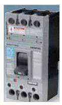
Figure Molded Case Circuit Breaker
The MCCB may be used as an incoming device, but it is more generally used as an outgoing device on the load side of a switchboard. It is normally mounted into a low-voltage switchboard
or a purpose-design ed panel board. In addition to the three features listed at the start of this section, it also includes:
• An electronic or thermal/electromagnetic trip sensing system to operate through the tripping mechanism and open the circuit breaker under overload or fault conditions
• All parts housed within a plastic molded housing made in two halves
• Current ratings usually from 10A to 1600A.
Miniature Circuit Breaker (MCB): Miniature circuit breakers rated current not more than 100A. Trip characteristics normally not adjustable. The miniature circuit breaker (MCB) has a contact system and means of arc quenching, a mechanism and tripping and protection system to open the
circuit breaker under fault conditions.. Early devices were generally of the ‘zero-cutting’ type, and during a short circuit the current had to pass through a zero before the arc was extinguished;
this provided a short-circuit breaking capacity of about 3kA. Most of these early MCBs were
housed in Bakelite moldings. The modern MC B is a much smaller and more sophisticated device. All the recent developments associated with molded case circuit breakers have been incorporated into MCBs to improve their performance, and with breaking capacities of 10 kA to
16 kA now available, MCBs are used in all areas of commerce and industry as a reliable means of protection. Most MCBs are of single-pole construction for use in single-phase circuits.
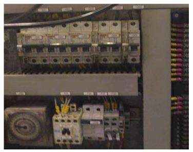
Figure – Miniature circuit Breaker
Medium Voltage Circuit Breakers
Medium-voltage circuit breakers rated between 619 Voltage and 11 kV assemble into metal- enclosed switchgear line ups for indoor use in MPS substation. Medium voltage circuit breakers
are also operated by current sensing protective relays operated through current transformers. Medium-voltage circuit breakers nearly always use separate current sensors and protective relays, instead of relying on built-in thermal or magnetic over current sensors.
Vacuum circuit breaker: Vacuum circuit breaker with rated current up to 3000 A, these breakers interrupts the current by creating and extinguishing the arc in a vacuum container. These are generally applied for voltages up to about 35,000 V but PS use vacuum circuit breaker
for 11KV which corresponds roughly to the medium-voltage range of power systems. Vacuum circuit breakers tend to have longer life expectancies between overhaul than do air circuit breakers. Vacuum circuit breakers tend to have longer life expectancies between overhaul th an do air circuit breakers.
In a vacuum circuit breaker, two electrical contacts are enclosed in a vacuum. One of the contacts is fixed, and one of the contacts is movable. When the circuit breaker detects a dangerous situation, the movable contact pulls away from the fixed contact, interrupting the current. Because the contacts are in a vacuum, arcing between the contacts is suppressed,
ensuring that the circuit remains open. As long as the circuit is open, it will not be energized.
Vacuum recluses will automatically reset when conditions are safe again, closing the circuit and
allowing electricity to flow through it. Re-closers can usually go through several cycles before they will need to be manually reset
Vacuum interrupters, mounted vertically within the circuit breaker frame, perform the circuit breaker interruption. Consisting of a pair of butt contacts, one movable and one fixed, interrupters require only a short contact gap for circuit interruption. The resulting high-speed operation allows the entire operating sequence, from fault to clear, to be consistently performed in three cycles or less.
The primary connection to the associated switchgear is through the six primary disconnects
mounted horizontally at the rear of the circuit breaker. Do not subject the primary disconnects to rough treatment. The operating mechanism is of the stored energy type. It uses charged springs to perform breaker opening and closing functions. The operating mechanism contains all necessary controls and interlocks. It is mounted at the front of the circuit breaker for easy access
during inspection and maintenance.
Specification of Vacuum circuit breaker:
• Rated frequency-50 -60Hz
• Rated making Current-10 Peak kA
• Rated Voltage-11kV
• Supply Voltage Closing-220 V/DC
• Rated Current-1250 A
• Supply Voltage Tripping-220 V/DC
• Insulation Lev el-IMP 75 kVP
• Rated Short Time Current-40 kA (3 SEC)
High-voltage circuit breakers
Electrical power transmission networks are protected and controlled b y high-voltage breakers.
The definition of high voltage varies but in power transmission work is usually thought to be
72.5 kV or higher. In MPS used SF6 circuit breaker for high voltage in sub station .High-voltage
breakers are always solenoid-operated, with current sensing protective relays operated through current transformers. In substations the protective relay scheme can be complex, protecting equipment and busses from various types of overload or ground/earth fault.
FUSES:
A fuse is a short piece of wire or thin strip which melts when excessive current flows through it for sufficient time. It is inserted in series with the circuit to be protected. Under normal operating conditions the fuse element it at a temperature below its melting point. Therefore, it carries the normal load current without overheating. However when a short circuit or overload occurs, the current through the fuse element increases beyond its rated capacity. This raises the temperature and the fuse element melts (or blows out), disconnecting the circuit protected by Init. electronics and electrical engineering a fuse (short for fusible link) is a type of sacrificial over current protection device. Its essential component is a metal wire or strip that melts when too much current flows, which
interrupts the circuit in which it is connected. Short circuit, overload or device failure is often the reason for excessive current.
Fuse Ratings:
Ampere Rating
Each fuse has a specific ampere rating, which is its continuous current-carrying capability. There are different types of fuse used in MPS, rating start from 2A.
Voltage Rating The voltage rating of a f use must be at least equal to the circuit voltage. The voltage rating of a fuse can be higher than the circuit voltage, but never lower. A 500 volt fuse, for example, could be used in a 450 volt circuit, but a 350 volt fuse could not be used in a 500 volt circuit.
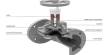
Magnetic Contactor
A magnetic contactor is a relay-controlled switch used to turn a power control circuit on and off.It is electrically controlled and uses less power than other circuits. A magnetic contactor comes in different forms and capacities.Magnetic contactors are a form of electrical relay found on most electrically powered motors. They act as a go-between for direct power sources, and high-load electrical motors in order to homogenize or balance out changes in electrical frequency which may come from a power supply as well as to act as a safeguard
Components
A magnetic contactor has three parts: power contacts, contact springs and auxiliary contacts. The power contact creates, carries and breaks the current in a magnetic contactor. The contact springs create a sufficient amount of pressure on the contacts. Auxiliary contacts perform signaling and interlocking maneuvers. Contactors vary in size and capacity. In heavy duty magnetic Conductors, blowout coils perform magnetic blowouts so the current can go further with more power. Economizer circuits decrease the power needed to keep the contactor closed; these are usually found in direct-circuit contactor coils working to keep the contactor cooler..
Input
A basic magnetic conductor has a coil input that is driven by either a DC or AC supply, and it can be energized at the same voltage as the motor. It can also be controlled separately using programmable controllers and low voltage pilot devices. Most contactors handle lighting,
Heating, electric motors and capacitor banks
Function of Magnetic conductor
Contactors are usually fitted on open contacts, an d are designed to suppress and control electric arcs which are produced by interrupting heavy motor currents. They work on the principle of electromagnetism and the electricity runs through the coil from the core of the contactor. While the core is moving, a force is developed that allows the electromagnet to carry charge and hold the contacts together. Once the contactor coil is de-energized, the spring of the electromagnet returns to its original position.
Specification of Magnetic conductor:
Manufacturer : Siemens
Model : LC1-D1210M7
Origin : German
Coil Voltage : 220V AC Voltage : 415V
Frequency : 50/60 Hz
Changeover
A changeover switch for a tap changer including a pair of load switches. A diverter switch allows load to be diverted along a second path when its associated main switch is opened or closed. An auxiliary circuit has an auxiliary switch and a varistor connected in parallel across the
secondary of a transformer. When the auxiliary switch is opened the varistor impedance is reflected onto the primary of the transformer which causes the current in the main switch to divert through the diverter switch so that the main switch can be opened or closed with substantially no load on it.
Manual Change over Switch
The Manual change over switch is wired into your Electrical Distribution Board in your home or office allowing it to power particular appliances in your home or office by providing power to specific circuits.
The manual change over switch can be used with the remote start button. The Generator does however need time to get up to speed before the Manual Change Over Switch can be placed on “Generator.” The recommended time for this is 5 Seconds. Hence when used in conjunction with a remote start button, the generator should be started whilst the Manual Change over Switch is in the “Off” position. Once started and run for the recommended time the
switch can be moved to “Generator” providing power to the relative circuits which the generator has been wired up to provide power to.The Following are the respective Model numbers associated with the Manual change over switches and their capability of single or three phase power. The key on the generator has to be in the ON position for the manual change over switch to work. The manual change over switch does not charge the battery so should the key be left in the on position the battery will go flat, if
the generator is not used on a regular basis.
Protective Relaying and Protection
Protective relays are used to detect defective lines or apparatus and to initiate the operation of circuit interrupting devices to isolate the defective equipment. Relays are also used to detect abnormal or undesirable operating conditions other than those caused by defective equipment and either operates an alarm or initiate operation of circuit- interrupting dev ices A protection relay is a device that senses any change in the signal which it is receiving, usually from a current and/or voltage source. If the magnitude of the incoming signal is outside a preset range, the relay will operate, generally to close or open electrical contacts to initiate some further operation, for example the tripping of a circuit breaker.
Characteristic of relay:
Protection relays can be classified in accordance with the function which they carry out, their construction, the incoming signal and the type of functioning.
General function:
• Protection.
• Monitoring.
• Control .
Construction:
• Electromagnetic.
• Solid state.
• Microprocessor.
• Computerized.
• Incoming signal:
• Current.
• Voltage.
• Frequency.
Type of protection
• Over current.
• Directional over current.
• Distance.
• Over voltage.
• Differential.
• Reverse power.
over current and over voltage relay:
The Over current and over voltage relay responds to a magnitude of over current and over voltage above a specified value. There are four basic types of construction: They are plunger, rotating disc, static, an d microprocessor type. In the plunger type, a plunger is moved by magnetic attraction when the cur rent exceeds a specified value. In the rotating induction-disc
type, which is a motor, the disc rotates by electromagnetic induction when the current exceeds a specified value. Static types convert the cur rent to a proportional D.C mill volt signal and apply it to a level detector with voltage or contact output. Such relays can be designed to have various current-versus-time operating characteristics. In a special type o f rotating induction-disc relay, called the voltage restrained over current relay.
The magnitude of voltage restrains the operation of the disc until the magnitude of the voltage drops below a threshold value. Static over current relays are equipped with multiple curve characteristics and can duplicate almost any shape of electromechanical relay curve.
Microprocessor relays convert the current and voltage to a digital signal. The digital signal can then be compared to the setting values input into the relay. With the microprocessor relay, various curves or multiple time-delay settings can be input to set the relay operation. Some relays
allow the user to define the curve with points or calculations to determine the output characteristics.
Distance Relay
The distance relay responds to a combination of both voltage and current. The voltage restrains operation, and the fault current causes operation that has the overall effect of measuring impedance. The relay operates instantaneously (within a few cycles) on a 60-cycle basis for values of impedance below the set value. When time delay is required, the relays energizes a
separate time-delay relay or function with the contacts or output of this time-delay relay or function performing the desired output functions. The relay operates on the magnitude of impedance measured by the combination of restraint voltage and the operating current passing through it according to the settings applied to the relay.
When the impedance is such that the impedance point is within the impedance characteristic circle, the relay will trip. The relay is inherently directional. The line impedance typically corresponds to the diameter of the circle with the reach of the relay being the diameter of the circle.
Differential Relay
The differential relay is a current-operated relay that responds to the difference between two or more device currents above a set value. The relay works on the basis of the differential principle
That what goes into the device has to come out .If the current does not add to zero, the error current flows to cause the relay to operate and trip the circuit. The differential relay is used to provide internal fault protection to equipment such as transformers, generators, and buses.
Relays are designed to permit differences in the input currents as a result of current transformer mismatch and applications where the input currents come from different system voltages, such as transformers. A current differential relay provides restraint coils on the incoming current circuits.
The restraint coils in combination with the operating coil provide an operation curve, above
which the relay will operate. Differential relays are often used with a lockout relay to trip all power sources to the device and prevent the device from being automatically or remotely re- energized. These relays are very sensitive. The operation of the device usually means major problems with the protected equipment and the likely failure in re-energizing the equipment
Directional Over current Relay
A directional over current relay operates only for excessive current flow in a given direction. Directional over current relays are available in electromechanical, static, and microprocessor constructions. An electromechanical overcorrect relay is made directional b y adding a directional
unit that prevents the over current relay from operating until the directional unit has operated. The directional unit responds to the product of the magnitude of current, voltage, and the phase angle between them or to the product of two currents and the phase angle between them. The value of this product necessary to provide operation of the directional unit is small, so that it will not limit the sensitivity of the relay (such as an over current relay that it controls). In most cases, the directional element is mounted inside the same case as the relay it controls. For example, an
over current relay and a directional element are mounted in the same case, and the combination is called a directional over current relay. Microprocessor relays often provide a choice as to the polarizing method that can be used in providing the direction of fault, such as applying residual current or voltage or negative sequence current or voltage polarizing functions to the relay.
Distribution board:
A distribution board (or panel) is a component of an electricity supply system which divides an electrical power feed into subsidiary circuits, while providing a protective fuse or circuit breaker for each circuit, in a common enclosure . Normally, a main switch , and in recent boards, one or more Residual-current devices (RCD) or Residual Current Breakers with Overecurrent protection (RCBO), will also be
Maintenance Instruments of List
1 . Multi-meter (AVO)
2. Multi Screw Driver set
3. Pliers
4. Noose Pliers
5. Cutting Pliers
6. Hammer
7. Tester
8. Series Lamp
9. Wire Striper
10. Spanner set
11. Adjustable wrench
12. Clip-on meter
13. Soldering Iron
14. Griper Pliers
15. Punching etc.
CONCLUSION:
I joint to BSRM Ltd. Factory for internship. This factory of all worker and management is very good and helpfully. Their help for my internship period happen be easy, therefore I would highly obliged. There, I learn to 11kv/.440kv Sub-station, Generator, Switchgear and factory maintenance division of equipments are working principle, competent and possible causes solution. Hare, many new machine, instruments & tools about understood. There are many problem to face and their with try to solution. This is my new experience. I am very enjoy the internship period, because it a new situation, new work and new problem solution invention and new learn of goods are characters. I hope this experience will need of my service and my future.
![Report on Models for Nanometer Size MESFETs [ Part-1 ]](https://assignmentpoint.com/wp-content/uploads/2013/04/MESFET-200x100.jpg)