Generation:
Much of the energy we use is produced in large power plants. Those plants extract the energy from some source, such as coal, and change that energy into the energy of choice, electricity. Then that electrical energy can be transported to where it is needed. Contrary to what you might expect, the source energy goes though a number of changes before being turned into electrical energy, leading to a chain of energy changes.
Classification: According to base
1) Base load power plant
2) Peak load power plant
Base load power plant:
Base load (also base load, or base load demand) is the minimum amount of power that a utility or distribution company must make available to its customers, or the amount of power required to meet minimum demands based on reasonable expectations of customer requirements. Base load values typically vary from hour to hour in most commercial and industrial areas.
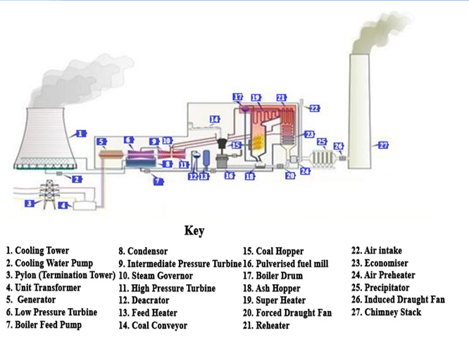
Fig : Base load power plant
Base load plant, (also base load power plant or base load power station) is an energy plant devoted to the production of base load supply. Base load plants are the production facilities used to meet some or all of a given region’s continuous energy demand, and produce energy at a constant rate, usually at a low cost relative to other production facilities available to the system.
Examples of base load plants using nonrenewable fuels include nuclear and coal-fired plants. Among the renewable energy sources, hydroelectric, geothermal, biogas, biomass, solar thermal with storage and ocean thermal energy conversion can provide base load power. Base load plants typically run at all times through the year except in the case of repairs or scheduled maintenance. Hydroelectric power also has the desirable attribute of dispatch ability, but a hydroelectric plant may run low on its fuel (water at the reservoir elevation) if a long drought occurs over its drainage basin.
Each base load power plant on a grid is allotted a specific amount of the base load power demand to handle. The base load power is determined by the load duration curve of the system. For a typical power system, the rule of thumb is that the base load power is usually 35-40% of the maximum load during the year.
Peaks or spikes in customer power demand are handled by smaller and more responsive types of power plants called peaking power plants, typically powered with gas turbines.
Whilst historically large power grids have had base load power plant to exclusively meet the base load, there is no specific technical requirement for this to be so. The base load can equally well be met by the appropriate quantity of intermittent power sources and peaking power plant.
Peak load power plant:
Peaking power plants, also known as peaker plants, and occasionally just “peakers,” are power plants that generally run only when there is a high demand, known as peak demand, for electricity. In the United States, peak hours usually occur in the afternoon, especially during the summer months when the air conditioning load is high. During this time many workplaces are still open and consuming power. Peak hours can also occur in the evening after work hours, when household appliances are heavily used.
A peaker plant may operate many hours a day or it may operate only a few hours per year, depending on the condition of the region’s electrical grid. Because of the cost of building an efficient power plant, if a peaker plant is only going to be run for a short or highly variable time it does not make economic sense to make it as efficient as a base load power plant. In addition, the equipment and fuels used in base load plants are often unsuitable for use in peaker plants because the fluctuating conditions would severely strain the equipment. For these reasons, nuclear, geothermal, waste-to-energy, coal, biomass andelectrochemical energy storage systems are rarely, if ever, operated as peaker plants.
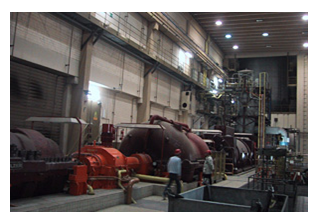
Fig : Peak Load Power Plant
In the US peaker plants are generally gas turbines that burn natural gas. A few burn petroleum-derived liquids, such as diesel oil and jet fuel, but they are usually more expensive than natural gas, so their use is limited. However, many peaker plants are able to use petroleum as a backup fuel. The thermodynamic efficiency of simple-cycle gas turbine power plants ranges from 20 to 42%, with between 30 to 42% being average for a new plant.
For greater efficiency, a heat recovery steam generator (HRSG) is added at the exhaust. This is known as a combined cycle plant. Cogeneration uses waste exhaust heat for process or other heating uses. Both of these options are used only in plants that are intended to be operated for longer periods than usual. Natural gas and diesel generators with reciprocating engines are sometimes used for grid support using smaller plants.
Classification: According to fuel
1) Fossil-fuel power stations
2) Nuclear power plants
3) Geothermal power plants
4) Binary cycle power plants
5) Biomass-fuelled power plants
6) Solar thermal
Fossil-fuel power stations:
A fossil-fuel power station is a type of power station that burns fossil fuels such as coal, natural gas or petroleum (oil) to produce electricity. Central station fossil-fuel power plants are designed on a large scale for continuous operation. In many countries, such plants provide most of the electrical energy used.
Fossil fuel power stations have rotating machinery to convert the heat energy of combustion into mechanical energy, which then operates an electrical generator. The prime mover may be a steam turbine, a gas turbine or, in small plants, a reciprocating internal combustion engine. All plants use the energy extracted from expanding gas – steam or combustion gases. A very few MHD generators have been built which directly convert the energy of moving hot gas into electricity.
Let’s look at a typical coal fired power plant.
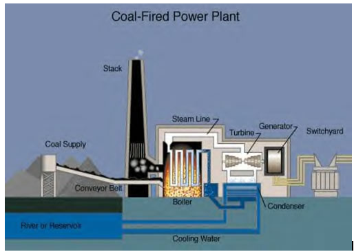
Fig Fossil Fuel Generation
Here, the coal is burned in a boiler which produces steam. The steam is run through a turbine which turns a generator which produces electricity. A turbine is like a fan in reverse, with many vanes or blades, where the steam is used to make the turbine turn or rotate rapidly. A generator is a huge magnet that is turned by the turbine. As the magnet turns inside a coil of wire, electricity is produced. So, the energy chain for this power plant would look like this:
| Chemical | Heat | Mechanical | Electrical |
The huge magnet assists in changing the mechanical energy into electrical energy, but the mechanical energy does not actually turn into magnetic energy. This is complicated since electrical and magnetic energy are so intimately related to one another.
Environment impact: World organizations and international agencies, like the IEA, are concerned about the environmental impact of burning fossil fuels, and coal in particular. The combustion of coal contributes the most to acid rain and air pollution.
Acid rain is caused by the emission of nitrogen oxides and sulfur dioxide. These gases may be only mildly acidic themselves, yet when they react with the atmosphere, they create acidic compounds such as sulfurous acid, nitric acid and sulfuric acid which fall as rain, hence the term acid rain. In Europe and the U.S.A., stricter emission laws and decline in heavy industries have reduced the environmental hazards associated with this problem, leading to lower emissions after their peak in 1960s.
In 2008, the European Environment Agency (EEA) documented fuel-dependent emission factors based on actual emissions from power plants in the European Union.
Pollutant | Hard coal | Brown coal | Fuel oil | Other oil | Gas |
CO2 (g/GJ) | 94,600 | 101,000 | 77,400 | 74,100 | 56,100 |
SO2 (g/GJ) | 765 | 1,361 | 1,350 | 228 | 0.68 |
NOx (g/GJ) | 292 | 183 | 195 | 129 | 93.3 |
CO (g/GJ) | 89.1 | 89.1 | 15.7 | 15.7 | 14.5 |
Non methane organic compounds (g/GJ) | 4.92 | 7.78 | 3.70 | 3.24 | 1.58 |
Particulate matter (g/GJ) | 1,203 | 3,254 | 16 | 1.91 | 0.1 |
Flue gas volume total (m3/GJ) | 360 | 444 | 279 | 276 | 272 |
Nuclear power plants:
A nuclear power plant is a thermal power station in which the heat source is a nuclear reactor. As in a conventional thermal power station the heat is used to generate steam which drives a steam turbine connected to a generator which produces electricity. As of February 2, 2012, there were 439 nuclear power plants in operation.
Let’s look at a typical Nuclear power plant.
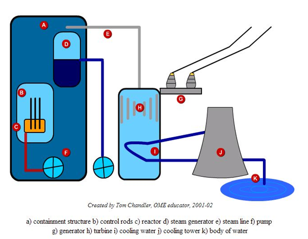
Fig : Nuclear power plants
Uranium is usually formed into pellets which are arranged into long rods, and the rods are collected together into bundles. The bundles are then submerged in water inside a pressure vessel or reactor. The fission reaction is a chain reaction, each uranium atom that fissions or breaks apart gives off two neutrons that will cause two more atoms to fission. To prevent this, control rods made of a material that absorbs neutrons are inserted into the bundle using a mechanism that can raise or lower the control rods.
The uranium bundle acts as an extremely high-energy source of heat. It heats the water and turns it to steam. The steam drives a steam turbine, which spins a generator to produce electricity. The animation below illustrates this process.
The energy chain for a nuclear power plant is nearly identical to the coal power plant. The only difference is the initial or source of energy, which is nuclear instead of chemical.
Nuclear | Heat | Mechanical | Electrical |
Complexity:
Nuclear power plants are some of the most sophisticated and complex energy systems ever designed. Any complex system, no matter how well it is designed and engineered, cannot be deemed failure-proof. Stephanie Cooke has said that:
The reactors themselves were enormously complex machines with an incalculable number of things that could go wrong. When that happened at Three Mile Island in 1979, another fault line in the nuclear world was exposed. One malfunction led to another, and then to a series of others, until the core of the reactor itself began to melt, and even the world’s most highly trained nuclear engineers did not know how to respond. The accident revealed serious deficiencies in a system that was meant to protect public health and safety.
The 1979 Three Mile Island accident inspired Perrow’s book Normal Accidents, where a nuclear accident occurs, resulting from an unanticipated interaction of multiple failures in a complex system. TMI was an example of a normal accident because it was “unexpected, incomprehensible, uncontrollable and unavoidable”.
Perrow concluded that the failure at Three Mile Island was a consequence of the system’s immense complexity. Such modern high-risk systems, he realized, were prone to failures however well they were managed. It was inevitable that they would eventually suffer what he termed a ‘normal accident’. Therefore, he suggested, we might do better to contemplate a radical redesign, or if that was not possible, to abandon such technology entirely.
A fundamental issue related to complexity is that nuclear power systems have exceedingly long lifetimes. The timeframe involved from the start of construction of a commercial nuclear power station, through to the safe disposal of its last radioactive waste, may be 100 to 150 years.
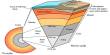
Geothermal power plants:
Geothermal electricity is electricity generated from geothermal energy. Technologies in use include dry steam power plants, flash steam power plants and binary cycle power plants. Geothermal electricity generation is currently used in 24 countries, while geothermal heating is in use in 70 countries.
Estimates of the electricity generating potential of geothermal energy vary from 35 to 2,000 GW. Current worldwide installed capacity is 10,715 megawatts (MW), with the largest capacity in the United States (3,086 MW), Philippines, and Indonesia.
Geothermal power is considered to be sustainable because the heat extraction is small compared with the Earth’s heat content. The emission intensity of existing geothermal electric plants is on average 122 kg of CO2 per megawatt-hour (MW·h) of electricity, about one-eighth of a conventional coal-fired plant.
Geothermal power stations type: Geothermal power stations are similar to other steam turbine thermal power stations – heat from a fuel source (in geothermal’s case, the earth’s core) is used to heat water or another working fluid. The working fluid is then used to turn a turbine of a generator, thereby producing electricity. The fluid is then cooled and returned to the heat source.
Dry steam power plants
Dry steam plants are the simplest and oldest design. They directly use geothermal steam of 150°C or greater to turn turbines.
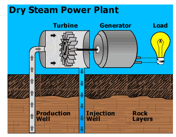
Fig : Flash Steam Power Plant
Binary cycle power plants:
Binary cycle power plants are the most recent development, and can accept fluid temperatures as low as 57°C. The moderately hot geothermal water is passed by a secondary fluid with a much lower boiling point than water. This causes the secondary fluid to flash vaporize, which then drives the turbines. This is the most common type of geothermal electricity plant being constructed today. Both Organic Rankine and Kalina cycles are used. The thermal efficiency of this type plant is typically about 10-13%.
The largest group of geothermal power plants in the world is located at The Geysers, a geothermal field in California, United States. As of 2004, five countries (El Salvador, Kenya, the Philippines, Iceland, and Costa Rica) generate more than 15% of their electricity from geothermal sources.
Geothermal electricity is generated in the 24 countries listed in the table below.
During 2005, contracts were placed for an additional 500 MW of electrical capacity in the United States, while there were also plants under construction in 11 other countries. Enhanced geothermal systems that are several kilometers in depth are operational in France and Germany and are being developed or evaluated in at least four other countries.
Environment impact: Fluids drawn from the deep earth carry a mixture of gases, notably carbon dioxide (CO2), hydrogen sulfide (H2S), methane (CH4), and ammonia (NH3). These pollutants contribute to global warming, acid rain, and noxious smells if released. Existing geothermal electric plants emit an average of 400 kg of CO2 per megawatt-hour (MW·h) of electricity, a small fraction of the emission intensity of conventional fossil fuel plants. Plants that experience high levels of acids and volatile chemicals are usually equipped with emission-control systems to reduce the exhaust. Geothermal plants could theoretically inject these gases back into the earth, as a form of carbon capture and storage.
In addition to dissolved gases, hot water from geothermal sources may hold in solution trace amounts of toxic chemicals, such as mercury, arsenic, boron, antimony, and salt. These chemicals come out of solution as the water cools, and can cause environmental damage if released. The modern practice of injecting geothermal fluids back into the Earth to stimulate production has the side benefit of reducing this environmental risk.
Biomass-fuelled power plants:
Biomass, as a renewable energy source, is biological material from living, or recently living organisms. As an energy source, biomass can either be used directly, or converted into other energy products such as biofuel.
In the first sense, biomass is plant matter used to generate electricity with steam turbines & gasifiers or produce heat, usually by direct combustion. Examples include forest residues (such as dead trees, branches and tree stumps), yard clippings, wood chips and even municipal solid waste. In the second sense, biomass includes plant or animal matter that can be converted into fibers or other industrial chemicals, including biofuels. Industrial biomass can be grown from numerous types of plants, including miscanthus, switchgrass, hemp, corn, poplar, willow, sorghum, sugarcane, bamboo, and a variety of tree species, ranging from eucalyptus to oil palm (palm oil).
As of early 2012, 85 of 107 biomass plants operating in the U.S. had been cited by federal or state regulators for violating clean air or water laws over the past five years. The Energy Information Administration projected that by 2017, biomass is expected to be about twice as expensive as natural gas, slightly more expensive than nuclear power, and much less expensive than solar panels.

As biomass is a natural material, many highly efficient biochemical processes have developed in nature to break down the molecules of which biomass is composed, and many of these biochemical conversion processes can be harnessed.
Biochemical conversion makes use of the enzymes of bacteria and other micro-organisms to break down biomass. In most cases micro-organisms are used to perform the conversion process: anaerobic digestion, fermentation and composting. Other chemical processes such as converting straight and waste vegetable oils into biodiesel are transesterification. Another way of breaking down biomass is by breaking down the carbohydrates and simple sugars to make alcohol. However, this process has not been perfected yet. Scientists are still researching the effects of converting biomass.
Biomass power plants work much like a fossil fuel power plant. A plant based product such as wood scraps, trees, switchgrass, corn stover, hemp, sugarcane, corn, yard clippings or even garbage, is combusted to heat water into steam. That steam spins an electric turbine and electricity is created.
Environment impact: The biomass power generating industry in the United States, which consists of approximately 11,000 MW of summer operating capacity actively supplying power to the grid, produces about 1.4 percent of the U.S. electricity supply.
Currently, the New Hope Power Partnership is the largest biomass power plant in North America. The 140 MW facility uses sugar cane fiber (bagasse) and recycled urban wood as fuel to generate enough power for its large milling and refining operations as well as to supply renewable electricity for nearly 60,000 homes. The facility reduces dependence on oil by more than one million barrels per year, and by recycling sugar cane and wood waste, preserves landfill space in urban communities in Florida.
Using biomass as a fuel produces air pollution in the form of carbon monoxide, carbon dioxide, NOx (nitrogen oxides), VOCs (volatile organic compounds), particulates and other pollutants, in some cases at levels above those from traditional fuel sources such as coal or natural gas. Black carbon – a pollutant created by incomplete combustion of fossil fuels, biofuels, and biomass – is possibly the second largest contributor to global warming. In 2009 a Swedish study of the giant brown haze that periodically covers large areas in South Asia determined that it had been principally produced by biomass burning and to a lesser extent by fossil-fuel burning. Researchers measured a significant concentration of 14C, which is associated with recent plant life rather than with fossil fuels.
Biomass systems can reduce waste energy from 66% to 25% compared to traditional fossil fuels , meaning a significantly smaller amount of input material (biomass) is used, therefore having a positive effect on the global environment and use of fuel.
Solar thermal:
Solar power is the conversion of sunlight into electricity, either directly using photovoltaics (PV), or indirectly using concentrated solar power(CSP). Concentrated solar power systems use lenses or mirrors and tracking systems to focus a large area of sunlight into a small beam. Photovoltaics convert light into electric current using the photoelectric effect.
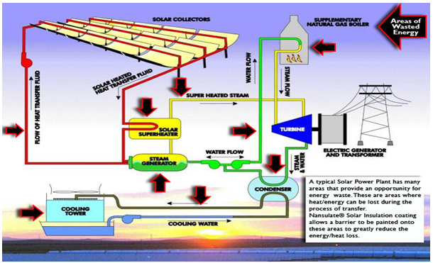
Fig : Concentrated solar power
Each of the ‘solar collectors’ is a trough-shaped mirror (with a parabolic cross-section) that tracks the sun and focuses the light on to a tube containing ‘heat transfer fluid’—which is normally some kind of oil. The hot oil passes through a ‘solar super heater’ and ‘steam generator’ where the heat boils water and creates superheated steam. The steam drives the turbine, the turbine drives the generator and that feeds electricity into the electricity transmission grid.
Steam that comes out of the turbine is still quite hot. It is fed through a condenser where it is cooled down by cooling water from a cooling tower. The cooled water is fed back into the steam generator and solar super heater to create superheated steam again, and this is fed back into the turbine to generate more electricity.
If there is not enough sun, superheated steam may be created using a ‘supplementary natural gas.
Although this is not shown in the diagram, some CSP plants can store solar heat in melted salts (e.g. nitrates of sodium or potassium) so that electricity generation may continue at night or on cloudy days.
Although this is not shown in the diagram, some CSP plants use sea water for cooling instead of a cooling tower. This has the effect of raising the temperature of the sea water so that, if a vacuum is applied, it gives off water vapour. The water vapour may be condensed to make fresh water—a very useful bonus in arid regions.
Environment impact: Unlike fossil fuel based technologies, solar power does not lead to any harmful emissions during operation, but the production of the panels leads to some amount of pollution.
Life cycle greenhouse gas emissions are now in the range of 25-32 g/kWh and this could decrease to 15 g/kWh in the future. For comparison (of weighted averages), a combined cycle gas-fired power plant emits some 400-599 g/kWh, an oil-fired power plant 893 g/kWh, a coal-fired power plant 915-994 g/kWh or with carbon capture and storage some 200 g/kWh, and a geothermal high-temp. power plant 91-122 g/kWh. Only wind and geothermal low-temp. are better, emitting 11 g/kWh and 0-1 g/kWh on average. Including the energy needed to mine uranium and the energy-intensity of power plant construction and decommissioning, some place nuclear power plants’ life-cycle greenhouse gas emissions below 40 g/kWh, but others give much higher figures. Using renewable energy sources in manufacturing and transportation would further drop carbon emissions. BP Solar owns two factories built by Solarex (one in Maryland, the other in Virginia) in which all of the energy used to manufacture solar panels is produced by solar panels. A 1-kilowatt system eliminates the burning of approximately 170 pounds of coal, 300 pounds of carbon dioxide from being released into the atmosphere, and saves up to 105 gallons of water consumption monthly.
Classification: According to Move
1) Steam turbine plants
2) Gas turbine plants
3) Combined cycle plants
Steam turbine plants
A steam turbine is a device that extracts thermal energy from
pressurized steam and uses it to do mechanical work on a rotating output shaft. Its modern manifestation was invented by Sir Charles Parsons in 1884.
Because the turbine generates rotary motion, it is particularly suited to be used to drive an electrical generator – about 90% of all electricity generation in the United States (1996) is by use of steam turbines. The steam turbine is a form of heat engine that derives much of its improvement in thermodynamic efficiency through the use of multiple stages in the expansion of the steam, which results in a closer approach to the ideal reversible process.
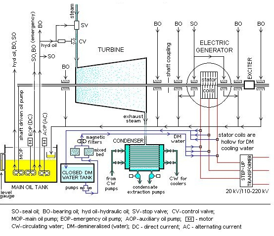
Fig : Turbine Generator System
Steam is first heated in a boiler, where it reaches a temperature of approximately 1,000 °F. It enters the turbine at a speed greater than 1,000 mph. The first valve that the steam encounters as it goes from the boiler to the turbine is the Main Stop Valve (MSV), which is either fully open or fully closed. The MSV does not control the steam flow other than to completely stop it. The terms “throttle pressure” and “throttle conditions” refer to steam as it is entering the MSV. The steam hits the first row of blades at elevated pressure. Its pressure is so high, in fact, that it can produce a torque with just a small surface area. The steam’s impact causes the rotor to begin turning. As the turbine stages progress, however, the steam loses density, thus requiring increasingly large surface areas. For this reason, the size of the blades increases with each stage. When the steam leaves the turbine, it has dropped over 900 °F and has lost almost all of its elevated pressure. Most of the pressure drop occurs across the diaphragm, which is a component between the outer wall and inner web. Its partitions direct the steam at the rotating blades.
The steam must strike the blades at a specific angle that will maximize the useful work of the steam’s high pressure. This is where nozzles come into play. Stationary rings of nozzles are placed between blade wheels to “turn” the steam at the optimal angle for striking the blades. A thrust bearing is mounted at one end of the main shaft to maintain its axial position and keep the moving parts from colliding with stationary parts. The journal bearing supports the main shaft and restricts it from springing out of its casing at high speeds.
The exhaust hood guides steam from the last stage of the turbine, and it is designed to minimize pressure loss, which would decrease the thermal efficiency of the turbine. After the steam leaves the exhaust section of the turbine, it enters a condenser, where it is cooled to its liquid state. The process of condensing the steam creates a vacuum, which then brings in more steam from the turbine. The water is returned to the boiler, reheated, and used again.
Fig : Steam Turbine Plant
The governor is a device that controls the speed of the turbine. Modern turbines have an electronic governor that uses a sensor to monitor the turbine speed by “looking” at the rotor teeth. The Ventilator Valve (VV) also aids in controlling the turbine’s speed. The VV is normally closed, but in an over speed situation, it drains steam. This steam comes from the reheat section, which is forcing steam back through the turbine, and is used to cool the high-pressure section.
Gas turbine plants
A gas turbine, also called a combustion turbine, is a type of internal combustion engine. It has an upstream rotating compressor coupled to a downstream turbine, and a combustion chamber in-between.
Energy is added to the gas stream in the combustor, where fuel is mixed with air and ignited. In the high pressure environment of the combustor, combustion of the fuel increases the temperature. The products of the combustion are forced into the turbine section. There, the high velocity and volume of the gas flow is directed through a nozzle over the turbine’s blades, spinning the turbine which powers the compressor and, for some turbines, drives their mechanical output. The energy given up to the turbine comes from the reduction in the temperature and pressure of the exhaust gas.
Gas turbine engines are, theoretically, extremely simple. They have 3 parts:
- A compressor to compress the incoming air to high pressure.
- A combustion area to burn the fuel and produce high pressure, high velocity gas.
- A turbine to extract the energy from the high pressure, high velocity gas flowing from the combustion chamber.
The following figure shows the general layout of an axial-flow gas turbine – the sort of engine which is found in driving the rotor of a helicopter.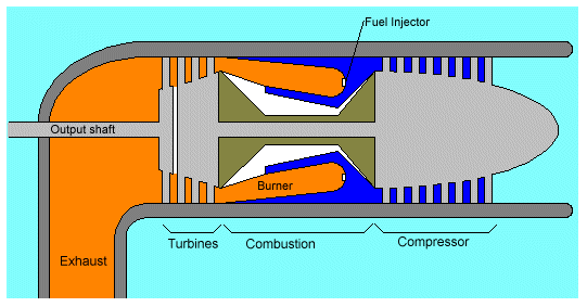
Fig: axial-flow gas turbine
In this engine air is sucked in from the right by the compressor. The compressor is basically a cone-shaped cylinder with small fan blades attached in rows (8 rows of blades are represented here). Assuming the light blue represents air at normal air pressure, then as the air is forced through the compression stage its pressure and velocity rise significantly. In some engines the pressure of the air can rise by a factor of 30. The high-pressure air produced by the compressor is in dark blue.
This high-pressure air then enters the combustion area, where a ring of fuel injectors injects a steady stream of fuel. The fuel is generally kerosene, jet fuel, propane, or natural gas. But in this design it impossible to blow out a candle where air moves at hundreds of miles per hour in combustion area. Here, a gadget is used which name is “Can”. The can is a hollow, perforated piece of heavy metal.

Fig : Half of the Can in cross-section
The injectors are at the right. Compressed air enters through the perforations. Exhaust gases exit at the left. In the previous figure that a second set of cylinders wraps around the inside and the outside of this perforated can, guiding the compressed intake air into the perforations.
As the left of the engine is the turbine section. In this figure there are two sets of turbines. The first set directly drives the compressor. The turbine, the shaft and the compressor all turn as a single unit: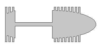
Fig : The turbine, the shaft and the compressor
At the far left is a final turbine stage, shown here with a single set of vanes. It drives the output shaft. This final turbine stage and the output shaft are completely stand-alone, freewheeling unit. They spin freely without any connection to the rest of the engine. And that is amazing part about a gas turbine engine – there is enough energy in the hot gases blowing through the blades of that final output turbine to generate 1,500 horsepower and drive a 63 ton M-1 Tank! A gas turbine engine really is that simple.
In the case of turbine used in a tank or a power plant, there really is nothing to do with the exhaust gases but vent them through an exhaust pipe, as shown. Sometimes the exhaust will run through some sort of heat exchanger either to extract the heat for some other purpose or to preheat air before it enters the combustion chamber.
Combined cycle plants
In electric power generation a combined cycle is an assembly of heat engines that work in tandem off the same source of heat, converting it into mechanical energy, which in turn usually drives electrical generators. The principle is that the exhaust of one heat engine is used as the heat source for another, thus extracting more useful energy from the heat, increasing the system’s overall efficiency. This works because heat engines are only able to use a portion of the energy their fuel generates (usually less than 50%). In an ordinary (non combined cycle) heat engine the remaining heat (e.g., hot exhaust fumes) from combustion is generally wasted.
Combining two or more thermodynamic cycles result in improved overall efficiency, reducing fuel costs. In stationary power plants, a widely used combination is a gas turbine (operating by the Brayton cycle) burning natural gas or synthesis gas from coal, whose hot exhaust powers a steam power plant (operating by the Rankine cycle). This is called a Combined Cycle Gas Turbine (CCGT) plant, and can achieve a thermal efficiency of around 60%, in contrast to a single cycle steam power plant which is limited to efficiencies of around 35-42%. Many new gas power plants in North America and Europe are of this type. Such an arrangement is also used for marine propulsion, and is called a combined gas and steam (COGAS) plant. Multiple stage turbine or steam cycles are also common.
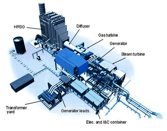
Fig : Combined cycle natural gas power plant.
The primary parts of a combined cycle natural gas power plant are a gas turbine, a steam generator and steam turbines. Compressed air is mixed with natural gas in the combustion chamber, and burns at high temperature (900 to 1500°C). The exhaust gas expands through a turbine. The turbine drives the compressor, but generates more work than what is used for compression, typically at a 2 to 1 ratio. This is caused by the change of temperature in the air flow as it passes through the combustion chamber. The process is essentially the same as you would find in a jet engine, but while a jet engine is constructed to generate thrust, and therefore has a turbine only big enough to drive the compressor, a gas turbine is bigger, using the excess energy to run a generator.
The hot exhaust gas (450 to 650°C) expands though a Heat Recovery Steam Generator (HRSG) which generates steam at typically about 550°C and high pressure (30-120 bar), and is expanded through one or several steam turbines (large/high temperature units may be fitted with multiple pressure HRSG with reheaters, while smaller units often do not). The gas turbine and the steam turbine(s) may be fitted on the same drive shaft, particularly in smaller units. 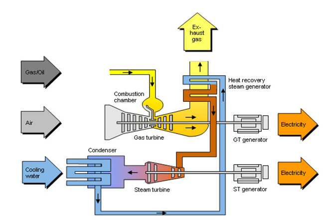
Schematic representation of a combined cycle power plant.
The steam turbine cycle converts about 30 to 40% of the thermal energy of the exhaust gas to work, increasing the total efficiency off the unit by about 20 percentage points.
As gas turbines are based on heat expansion of compressed air, combustion gases makes up only a small portion of the exhaust gas from the turbine. Therefore, the CO2 concentration (3 to 4%) and CO2 partial pressure (0.03 to 0.04 bar) in the flue gas is much lower than in thermal power plants (12 to 14% concentration and 0.12 to 0.14 bar partial pressure). This makes capturing the CO2 more challenging. However, the higher overall efficiency of CCPP units might make the portion of the total electric generation needed to run the capture process smaller than is the case in lower efficiency single cycle units, offsetting the higher energy cost pr unit of captured CO2.
The electric efficiency of a combined cycle power station, calculated as electric energy produced as a percent of the heating value of the fuel consumed, may be as high as 58%. As with single cycle thermal units, combined cycle units may also deliver low temperature heat energy for industrial processes, district heating and other uses. This is called cogeneration and such power plants are often referred to as a Combined Heat and Power (CHP) plant.