Over view of Differential Relay:
While over-current, voltage, distance and directionality are powerful techniques, all of them involve some compromise between the objectives of reliability, security, speed, selectivity and economy. Differential protection is different. It is profoundly simple, inherently secure, highly reliable, fast, and reasonably economical. As a result, differential protection is the most important concept in protection. The concept is a direct extension of Kirchoff’s current law – the sum of all currents into a region must be zero. Current transformers are placed at each electrical terminal of the protected zone and wired together as indicated within the zone. For external faults, where fault current passes through both CTs as same ratio.
The zone, current circulates in the current transformer secondary without passing through the relay. If the fault is internal to the zone, then the currents introduced into the current transformer secondary oppose each other and are forced to flow through the relay. The basics of a differential application include:
- CT at each power connection to the protected zone
- All CT’s have the same rating
- Careful attention to assure proper ct connections
- Differential protection is primary protection: it cannot provide backup protection for remote zones[Reference-1]
Introduction:
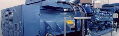
Synchronous generator is the most important element of power system. Generators do experience short circuits and abnormal electrical conditions. In many cases, equipment damage due to these events can be reduced or prevented by proper generator protection. Generators, unlike some other power system components, need to be protected not only from short circuits, but also from abnormal operating conditions.
Examples of such abnormal conditions are over-load, over-excitation, over-voltage, and loss of field, unbalanced currents, reverse power, and abnormal frequency. When subjected to these conditions, damage or complete failure can occur within seconds, thus requiring automatic detection and tripping. All faults associated with synchronous generators may be classified as either insulation failures or abnormal running conditions. An insulation failure in the stator winding will result in an inter-turn fault, a phase fault or a ground fault, but most commonly the latter since most insulation failures eventually bring the winding into direct contact with the core. Differential relays, in particular the digital ones are used to detect stator faults of generators.
Electric power utilities and industrial plants tradionally use electromechanical and solid-state relays for protecting synchronous generators [3]. With the advent of digital technology, researchers and designers have made significant progress in developing protection systems based on digital and microprocessor techniques [4], [5]. Several microprocessor based algorithms for detecting stator winding faults have been proposed.
[Reference-2]
Theory
Differential protection compares two (or more) currents to locate a fault; which actually makes current protection. In comparison with other types of protection, differential current protection pros-senses, an absolute selectivity in the sense that it operates smartly only in those cases where the fault is within the protected zone, and does not operates at all if the fault is out of its zone. The zone of the differential relay is limited by a part of the electric circuit between the current transformers (CTs), to which the relay is connected. Due to such high selectivity of protection, there is no need to activate a delay for the relay pick-up, which is why all differential relays are high speed. That being so, extraordinarily high selectivity and high speed of operation are the distinguishing features of differential protection.
Differential protection of power generator is divided into longitudinal protection and transverse protection. The former refers to protection of longitudinal sections of single lines (which is of course why it is called “longitudinal”), and the latter to the protection of parallel lines (comparing currents in these parallel lines).
Longitudinal differential protection operates on the principle of comparison of magna- fade and phase of the currents entering and leaving the protected circuit section or element. To accomplish differential protection, two CT’s (CT1 and CT2), having identical ratios of transformation, are interposed in the circuit at both ends of the protected circuit element. These C-Ts have their secondary interconnected by the connecting leads as shown for one phase in Figure4. 1.
[Reference-3]
The differential relay Relay is arranged the connection its secondary windings are parallel (CTs interconnection leads) with maintain its correct polarities. This scheme, based on the circulation of currents, was first established at the end of 19th centuries by Merz and Price and called the “: Merz-Price differential scheme.” This fundamental principle has formed the basis of many highly developed protective arrangements. If the secondary currents of CTs CT1 and CT2 are denoted, respectively, by I1 and I2, and the positive, direction of the current in the relay is taken to be that of current I1, during normal operating conditions on line AB (here and hereinafter vector values):
IREAL= I1-I2
This relation is valid by virtue of the fact that the impedance of the winding of relay (usually a current relay) is considerably less than that of the current transformer secondary windings and it can hence be considered that the secondary currents flow through interconnection leads and complete their circuit through the relay winding. In the ideal case during normal operating conditions and in the event of external short circuits ( outside the zone of protection), the secondary currents of CTs CT1 and CT2 will be equal in magnitude and opposite direction. Because of this, no current will flow in the differential relay circuit or:
In the actual circuit a current of unbalance will flow in the relay circuit because of the unequal magnitude of the CTs’ currents at one and the same primary current. This problem will be studied in greater detail below. When a short circuit occurs within the zone of protection and the power supply comes from one end (Figure 1.b), the relay circuit carries a current:
[ Reference-4]
The relays then operate to transmit an impulse to trip the circuit breaker at the supply end. When a short circuit occurs within the zone of protection and power is supplied from both ends (Figure 1.c), the sum of the secondary currents will flow through the relay,
Figure : Three-phase version of the scheme of differential protection of the generator’s stator with high-impedance differential relays. (a) Phase and earth fault protection; (b) Restricted earth fault protection.
These currents are general being different in magnitude. The relay in this case operates to transmit impulses to trip the circuit breakers at both ends of the faulted line.
The differential scheme studied here is called a “circulating-current circuit” due to the fact that the current continuously circulates in the interconnecting leads of this circuit. If two identical power lines are run in parallel from one substation to another and are connected
to the buses by a common circuit breaker, a common protection is installed for both lines and will trip out the circuit breaker when a short circuit occurs on any one of the lines. For protecting two parallel high-voltage lines of wide applications, transverse differential current protection is implemented, based on a comparison of the magnitude and phase of the currents in the parallel lines (Figure 2). As already mentioned above, the differential protection is applied not only (or protection of segments of lines, but also for protection of such important system components as transformers, reactors, generators. switchgears, power motors, etc. (Figure 3.)
[Reference-5]
Differential Protection of a Power Generator
Differential protection is a very reliable method of protecting generators, transformers, buses, and transmission lines from the effects of internal faults. Relays, which depend on excess of current for their operation, are less sensitive because they cannot make correct distinction between load conditions and minor fault conditions. In order to overcome this difficulty differential relays are used.
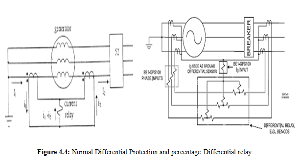
Figure : Normal Differential Protection and percentage Differential relay.
Differential relay is one that operates when the phasor difference of two or more similar electrical quantities exceed a predetermined value. Thus a current differential relay is one that compares the current entering a section of the system with current leaving the section.
Under normal operating conditions, the two currents are equal but as soon as fault occurs, this condition no longer applies. The difference between the incoming and outgoing currents is arranged to flow through relay operating coil. If this difference is equal to or grater than the pick up value the relay will operate and open the circuit breaker and isolate the faulty section.
Any type of relay when connected in a particular way can be made to operate as a differential relay. It is not the relay construction but the way in which relay is connected in a circuit makes it a differential relay.
In a differential protection scheme in the above figure, currents on both sides of the equipment are compared. The figure shows the connection only for one phase, but a similar connection is usually used in each phase of the protected equipment. Under normal conditions, or for a fault outside of the protected zone, current I1 is equal to current I2. Therefore the currents in the current transformers secondary are also equal, i.e. i1 = i2 and no current flows through the current relay.
If a fault develops inside of the protected zone, currents I1 and I2 are no longer equal, therefore i1 and i2 are not equal and there is a current flowing through the current relay.
[Reference-6]
Percentage Differential Relays
The disadvantage of the current differential protection is that current transformers must be identical; otherwise there will be current flowing through the current relays for faults outside of the protected zone or even under normal conditions. Sensitivity to the differential current due to the current transformer errors is reduced by percentage differential relays.
In percentage differential relays, the current from each current transformer flows through a restraint coil. The purpose of the restraint coil is to prevent undesired relay operation due to current transformer errors. The operating coil current | i1 – i2 | required for tripping is a percentage of the average current through the restraint coils.
Where k is the proportion of the operating coil current to the restraint coil current. For example if k = 0.1, the operating coil current must be more than 10% of the average restraint coil current in order for the relay to operate. Percentage Differential Relay (electronics type) which functions are the difference between two quantities of the same nature exceeds a fixed percentage of the smaller quantity. Also, it is known as biased relay; ratio-balance relay or ratio-differential relay.
[Reference -2]
Differential Protection
“A differential relay responds to vector difference between two or more similar electrical quantities”. From this definition the following aspects are known:
The differential relay has at least two actuating quantities say I1, I2.
- The two or more actuating quantities should be similar. i.e. Current/ Current.
- The relay responds to the vector difference between the two i.e.- to I1– I2, which includes magnitude and / or phase angle difference.
Differential protection is generally unit protection. The protected zone is exactly determined by location of CT’s or VT’s. The vector difference is achieved by suitable connections of current transformer or voltage transformer secondary.
[ Reference-7]
Operating Characteristics
The features which govern the operating characteristics are (a) current setting; and (b) operating time. The details are as follows:
- Current setting:
This setting determines its sensitivity on internal faults. The normal range of current setting varies from 10 to 100 percent of rated current.
- Operating Characteristics:
This depends on the type of relay and the magnitude of the differential current
Expressed as a multiple of this current setting. This time varies from about 25 to
500 ms at two times the current setting depending tin the type of relay.
Restraining Characteristics
The following restraining characteristics are used–one, two or all three of them, depending on requirements given below:
- Stability for external faults.
- Stability on magnetizing inrush.
- Stability during over-excitation inrush.
- Stability for external faults:
A differential relay may mal-operate on external faults due to C.T. saturation or C.T. mismatch. Ideally, C.T’s on both sides of the protected section should not saturate for external faults. However, because of different voltage levels, fault levels, ratios and makes, C.T’s on one side may saturate and cause spill current to flow through the operating relay resulting in unwanted operation.
Perfect matching of C.T.’s on both sides may not be practicable in all cases. Also tap change range provided on the protected transformer will automatically result in C.T. mismatch. This may also result in unwanted operation on external faults.
To ensure stability as required above on external faults, it is provided with a bias feature, usually expressed in terms of percentage bias defined as follows:
Bias settings normally provided vary from 5 to 50 percent depending on the particular application.
Self-biasing differential relays are also available in which the bias is automatically adjusted to the current setting. The characteristic of this type of relay is such that , it has a high sensitivity at low values of restraining current in order to ensure positive tripping on light internal faults. It will have a lower sensitivity at high values of restraint current to allow C.T.’s to depart from their true ratio under saturated conditions and also to prevent operation under through fault conditions. The , bias characteristic of this type of relay after about two times rated current is almost a vertical line and is independent of the current setting this is called a FORK characteristic.
[ Reference-7]
- Stability on magnetizing inrush current:
When a transformer primary is switched on to the supply source while the secondary is kept open, a transient magnetizing inrush current flows only on the primary side which appears as an internal fault to the differentially connected relays. Modern transformers are built from cold rolled steel having comparatively low hysteresis loss-magnetizing inrush current can approach the short circuit levels, i.e. 10 to 12 times full-load current with fairly long time constants of 40 to 60 seconds. The time constants may vary from 10 cycles for very small units to one minute for very large units.
The effect of source inductance is to reduce the magnitude of inrush current by reducing the magnitude of the excitation voltage. The time constant for the decaying inrush current is a function of the total resistance of the source plus that of the transformer winding. Hence transformers near the generating source have a longer inrush phenomenon, while at substations remote from the generating sources, the inrush is not as severe as the increased inductance and resistance of the line reduce the peak magnitude and damp the current.
- Stability during over-excitation inrush
With the advent of cold rolled grain oriented steel in transformer manufacture, modern power transformers are designed to operate at about 90 percent of the saturation flux densities at rated voltage. Hence during abnormal system conditions, short duration over voltage conditions can occur resulting in the saturation of the transformer cores, causing an increase in the excitation current of the transformer of the order of 10 to 100 times the normal value for a voltage rise of 20 to 30 per cent. This appears as an internal fault to the differential relay. Sometimes an additional restraint is provided by some manufacturers and this will be described later.
[ Reference-7]
Basic Unit
Feature and Characteristics
Standard equipment
- Modular design with automatic short circuiting C.T.-inputs
- Signal and data processing in a separate digital signal processor (32 samples per cycle)
- Digital filtering of measured quantities
- Three possibilities of parameter setting and data calling:
- Keyboard and display
- RS232 interface at the front (lap top)
- RS485 interface for integration into control systems at the rear
- Safety interlocking preventing parameter setting via different ways at the same time
- extensive internal plausibility check of modified parameters
- Event Recorder for recording system messages
- Fault Recorder for recording measured fault data
- Four programmable independent parameter sets
- Non-volatile memory for parameter sets, events and fault data
- Indication of measured operational values and resulting quantities
- Wide-ranging automatic self-tests
- Small relay size
- Three possibilities for relay resetting
- Indication of relay function optically or via separate self supervision relay
- All data interfaces galvanical isolated
- Rated frequency selectable: 50 Hz/60 Hz
[Reference-2]
Functions which can be programmed by the user
- Protection and system parameters
- Latched position or minimal signal duration for each of the output relays
Generator differential protection
- Stabilization against CT measuring errors
- No complete blocking of differential element but only reduced sensitivity Independent High Set differential element for heavy Faults
High- Impedance Differential Relays
The most simple design of this type is the so-called “high-impedance differential relays,” used for protection of concentrated objects such as switchgear, bus bars, generators, reactors, and power motors. The following limitations on CTs are required for applying these relays:
All C.Ts in the differential circuit must have the same ratio.
- All CTs should be operated on their full winding (i.e., tap connections must be given special consideration).
- Inlet and outlet current levels of protection object must be equivalent.
- No other equipment including no other types of protection devices can be connected to the CT used for high-impedance differential relays.
As already mentioned above, under external fault conditions if the CT has no error, the current in the secondary of the CT in the faulted line is equal and opposite to the vectorial sum of the currents in the secondary of the remaining CT in the same phase. No current flows in the relay and the voltage that appears across the paralleling points is zero. Unfortunately during fault conditions, CTs do not always perform ideally, since core saturation may cause a breakdown of ratio. Such core saturation usually is the result of a DC transient in the primary fault current, and may be aggravated by residual flux left in the core by a previous fault.
The worst condition of unbalanced secondary currents is realized when the CT in the faulted circuit is completely saturated and none of the other CTs suffer a reduction in ratio. Under this condition the saturated transformer secondary winding presents an impedance which is practically equal to its DC resistance, since the leakage reactance of the full s-hiding of the toroidally wound CT can be neglected and a secondary current will be forced through the saturated CT equal to the sum of the secondary currents in the remaining paralleled as, less the current through the high-impedance relay which is negligible. The maximum voltage across the relay under external fault conditions therefore, will be the resistance drop of the theoretical secondary current which flows through the leads and secondary winding of the saturated CT in the faulted line.
It is obvious that under external fault conditions, no higher voltage than this can exist, since either a reduction in ratio of any of the other CT’s or a diversion of current through the relay will reduce the current through the saturated transformer secondary. Whatever secondary voltage is generated by the core flux of the saturated CT will also reduce the voltage across the paralleling points. Therefore, in order to prevent incorrect operation under extreme values of external Faults, it is only necessary to set the pick-up of the relay above this maximum through- fault voltage4 which can readily be calculated from the resistance of the CT leads and this mode, which is enough for the relay pick-up. On one hand, these resistances effectively limit voltage in secondary circuits of the CT when a high-impedance differential relay (Figure 4) is used, and on the other hand they provide pick-up of the relay shunted by this resistance at a certain voltage level.
The working element of such a high-impedance differential relay is a voltage relay. Many companies produce such relays both of electromagnetic and electronic types. [Reference-2]
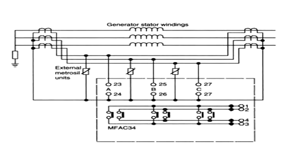
Figure : Connection diagram for high-impedance differential relay type.
Biased Differential Relays
In modern power systems transformers with ratings of more than about 1000 kVA are protected against internal short circuits by differential protection. The heart of this form of protection is the differential relay in which the current on the primary and secondary sides to the transformer to be protected are compared with respect to magnitude and phase relationship. [Reference-2]
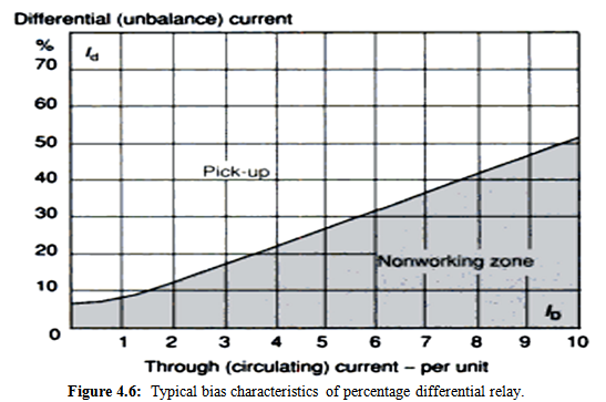
Figure : Typical bias characteristics of percentage differential relay.
In normal operation, the ratio between the primary and secondary currents is constant at any instant, apart from the magnetizing cu rent which appears on one side but which only amounts to a few percent of the rated current of the transformer, depending on the transformation ratio of the transformer. The phase relationship between the two currents is fixed by the vector group of the transformer. On occurrence of a fault inside the protected zone, restricted by the location of the CT’s necessary for connecting the differential protection on the high- and low-voltage sides of the transformer, this ratio of the currents, and in some circumstances their phase relationship, is disturbed The unbalanced current can be evaluated directly as a criterion of the fault. The differential relay responds to this current by closing its tripping contacts, causing the circuit breakers on the high- and low-voltage sides of the transformer to open.
Even under normal working conditions unbalanced currents (spill currents) appear, their magnitude depending on the individual ratio and phase-angle errors of the CT’s
employed. They generally increase as the load on the transformer increases. They attain particularly high values when through faults outside the protected zone the CT’s tend to saturate; and also in the case of tap-changing transformers, when (as is usual) the CT’s are not adjusted when the ratio of power transformation is changed. To compensate for these influences, the differential relay is stabilized, that is, the relay is given a characteristic basically similar to that in Figure 12.13. This shows the unbalance (differential) current I4 necessary to operate the differential relay in relation to the circulating current I. Differently, the increase of circulating current results in a desensitization of the relay to a differential current,
At low values of the circulating current the curve does not rise more steeply than is necessary with a view to the spill currents, and changes its slope only when the circulating currents are such that the as are approaching saturation.
In early electromagnetic differential relays (e.g., the QS4, produced by AEG) the comparison of the vector sums:
And the vector difference:
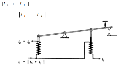
Figure : Schematic diagram of an electromagnetic percentage differential relay of the QS4 type.
General Idealized View
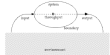
Differential protection is a strict selective object protection and is based on the current measuring principle at the input and output side of the object being protected. Dependent on the earthing method used, the neutral can also be included in measuring and balance.
The area between input and output CTs of the object is classed as protection zone supervised by the relay. Included in the protection zone are also CTs and CT connection wire to the relay. [Reference-2]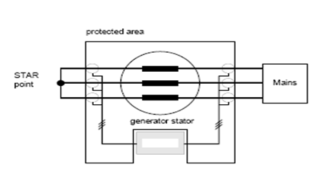
Figure: Definition of protection zone
The relay checks constantly if the incoming currents of a winding are met by respective outgoing currents. If the balance of the conductor currents shows a difference, this may suggest a fault within the protection zone.
It is Noted that:
Motors and generators are to be handled from the differential protection in the same way. To distinguish between faults occurring within (internally) or outside (externally) of the protection zone is the main purpose of the differential protection because at internal faults the differential protection relay must trip, but not so at external faults.
External fault
During a short circuit occurring at the grid, the short circuit current flows through the generator. The difference between incoming and outgoing currents of all generator terminals is small (in ideal cases = zero) I1-I2 = 0. The differential protection relay does not trip (Switching off in such cases probably to be realized by an over-current relay).
[Reference-2]
Internal fault
When an internal fault occurs the current balance is different. Dependent on the kind of fault a deficit in the total of incoming currents can be observed. A winding short circuit, for instance, can be fed from both sides, even if with different intensity. But this short circuit does not go through the generator; it is fed from both sides into the generator. So therefore the current balance shows a difference.
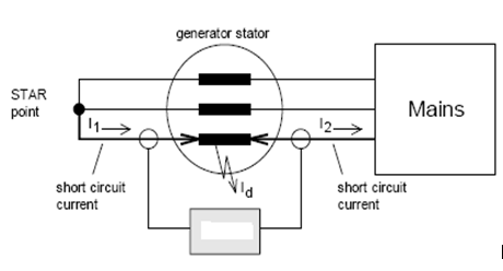
Figure: Internal fault (example of a short circuit fed from two sides)
Due to the chosen direction of the reference arrow, current I2 flows here in negative direction.
The differential relays detects a current difference of I1-I2 = Id and trips when Id has exceeded the set threshold. At first approximation this idealized view applies to stationary states only. In reality other effects, especially CT errors, may cause the established current difference to rise, even if there is no internal fault. In such cases a simple static differential relay would mistakenly trip and to prevent this stabilizing measures have to be taken. Possible sources of measuring errors are systematic and can be duly taken into account. Stabilizing the relay means always an action to make the relay more insensitive.
Fundamental analysis Distortion factors for differential current measuring are:
- Measuring errors of angle and value of the CTs used
- Poor adjustment of rated CT data to rated generator data by these factors a fault current is caused which mainly depends on the biasing current. This fault current is being measured as a differential current, although a generator fault must not necessarily have occurred. When the pickup current is set at a very sensitive value, each of these factors can cause unintended tripping. With increasing bias current the pickup current has to be corrected upwardly. The following pickup characteristic (exact characteristic) gives a detailed study of the individual fault factors and the resulting fault current.
In fig. 4.10 the expected fault current versus tripping characteristic is shown. If a real fault occurs, the measured differential current exceeds the biasing current caused by operational conditions. Therefore the pickup characteristic must exceed the biasing current characteristic by the required sensitivity value.
The exact course can be approximated by a simplified characteristic consisting of two linear sections (I and II). The higher the characteristic begins, the higher the permissible differential current. If the characteristic begins at a very low point this means maximum sensitivity. If the pickup characteristic is below the biasing characteristic, systematic effects can cause unintended trips. [Reference-8]
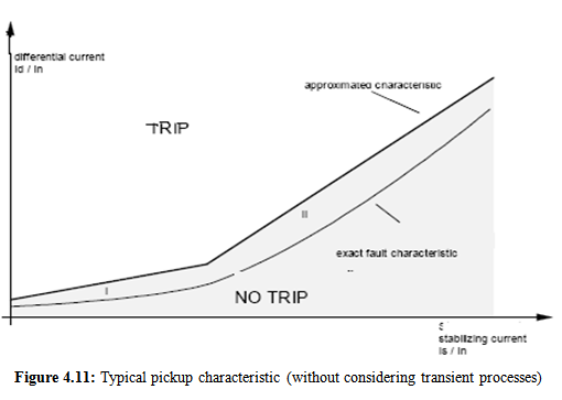
Figure : Typical pickup characteristic (without considering transient processes)
Calculation of the differential current and stabilizing current resulting from the fundamental oscillation (current of the positive phase sequence system) produces a point on the characteristic. If this point is within the tripping range, the output relay picks up.
Tripping procedure
The protection program permanently checks the measurements that the DSP (digital signal processor) delivers. When the DSP gives a new differential current, the protection task checks whether it lays within the tripping limits. If this is the case the relay is internally energized. Tripping occurs when the calculated difference current is consecutively three times within the tripping limits. To prevent the energized state from being reset too quickly, a hysteresis of 75 % is programmed. This means that a newly calculated difference current must be smaller than 75 % of the present characteristic trip value in order for the energized condition to be reset. The total tripping time of the Relay is below 35 ms. [Reference-3].
Conclusions:
A digital differential technique for detecting generator stator winding internal faults has been presented in this paper. ATP-EMTP software has been used for generating fault data and then processed in MATLAB to get fundamental frequency current phasors. These current phasors at both ends are calculated using recursive Discrete Fourier Transform algorithm. Current phasors at both ends of stator windings are used in differential algorithm to implement relay logic. Results of case studies of single line to ground and line to line fault are presented.
Case study results shows that the technique used correctly discriminates between internal and external faults on the stator winding. The results are applicable to other internal unsymmetrical faults also.
Reference:
1. M. S. Sachdev and D. W. Wind, “Generator differential protection using a hybrid computer,” IEEE Trans. Power Apparatus System, PAS-92 (1973) 2063-2072.
2. http://www.wikipedia.org.
3. M. S. Sachdev (Coordinator) Microprocessor Relays and Protections Systems, IEEE Tutorial Course Text, Power Engineering Society Special Publ. No.88 EH0269-1-PWR, IEEE, Piscatway, NJ, USA, 1988.
4. C. J. Mozina, IEEE Tutorial on the Protection of Synchronous Generators, IEEE Tutorial Course, IEEE Power Engineering Society Special Publ., no. 95 TP102, 1995.
5. “Protective Relays Applications Guide,” The English Electric Company Limited, Relay Division, Stafford, 1975.
6. Gabriel Benmouyal, Serge Barceloux, and Rolland Pelletier, “Field experience with a digital relay for synchronous generators,” IEEE Transactions on Power Delivery, vol. 7, no. 4, October 1992.
7. http://www. google.com.
8.(I)http://www.wikipedia.org/w/index.php?title=Special%3ASearch&redirs=1&search=internal+fault+of+generator&fulltext=Search&ns0=1 (II)“Protective Relays Applications Guide,” The English Electric Company Limited, Relay Division, Stafford, 1975.