Introduction
The purpose of the evaporator is to receive low-pressure, low-temperature fluid from the expansion valve and to bring it in close thermal contact with the load. The refrigerant takes up its latent heat from the load and leaves the evaporator as a dry gas. Evaporators are classified according to their refrigerant flow pattern and their function.
Flow pattern and function
The refrigerant flow pattern is dependent on the method of ensuring oil removed from the evaporator and possibly its return to the crankcase.
Flooded evaporators have a body of fluid boiling in a random manner, the vapor leaving at the top. In the case of ammonia, any oil present will fall to the bottom and be drawn off from the drain pot or oil drain connection. With the halocarbons, a proportion of the fluid is bleed off and rectified. Evaporators which keep the oil moving by means of continuous fluid velocity, until it gets back to the compressor suction, are termed dry expansion. In these, the refrigerant is totally evaporated.
The function of the evaporator will be to cool gas, liquid or other product load. In most cases air or a liquid is first cooled, and this is then use to cool the load. For example, in a cold room air is cooled and this air cools the stored produce and carries away heat leaking through the structure; in a water chiller system, the water is circulated to cool the load, etc.
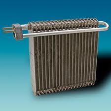
Air cooling evaporators
Air cooling evaporators for cold rooms, blast freezers, air-conditioning, etc, will have finned pipe coils. In all but very small coolers, there will be fans to blow the air over the coil.
Construction materials will be the same as for air-cooled condensers. Aluminum fins on copper tube are the most common for the halocarbons, with stainless steel or aluminum tube for ammonia.
Frost or condensed water will form on the fin surface and must be drained away. To permit this, fins will be vertical and the air flow horizontal, with a drain tray provided under.
The size of the tube will be such that the velocity of the boiling fluid within it will cause turbulence to promote heat transfer. Tube diameters will vary from 9 mm to 32 mm, according to the size of coil.
Fin spacing will be a compromise between compactness (and cost) and the tendency for the inter fin spaces to block with condensed moisture or frost. Spacing’s will vary from 2 mm on a compact air-conditioner to 12 mm on a low-temperature cold room coil.
Liquid cooling evaporators
Liquid cooling is mostly in shell-and-tube or shell-and-coil evaporators. In the shell-and-tube type, the liquid is usually in the pipes and the shell is some three-quarters full of the liquid, boiling refrigerant.
A number of tubes is omitted at the top of the shell to give space for the suction gas to escape clear of the surface without entraining liquid. Further features such as multiple outlet headers, suction trap domes and baffles will help to avoid liquid droplets entering the main suction pipe. Gas velocities should not exceed 3 m/s and lower figures are used by some designers.
Operated in this manner, the shell-and-tube type is a flooded evaporator and has coil drainage pots if using ammonia, or a mixture bleed system if the refrigeration is one of the halocarbons.
The speed of the liquid within the tubes should be about 1 m/s or more, to promote internal turbulence for good heat transfer. End cover baffles will constrain the flow to a number of passes, as with the shell-and-tube condenser.
a) Shell
b) Tube
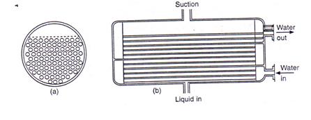
Figure : Shell-and-tube evaporator
Evaporators of this general type with dry expansion circuits will have the refrigerant within the tubes, in order to maintain a suitable continuous velocity for oil transport, and the liquid in the shell.
This can be made as shell-and-tube, with the refrigerant constrained to a number of passes, or may be shell-and-coil. In both these configurations, baffles are needed on the water side to improve the turbulence, and the tubes may be finned on the outside. Internal swirl strips or wires will help to keep liquid refrigerant in contact with the tube wall.
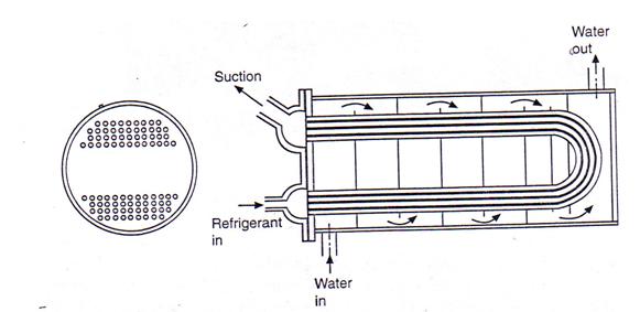
Figure : Shell-and-coil evaporator
Liquid cooling evaporators may comprise a pipe coil in an open tank, and can have flooded or dry expansion circuitry. Flooded coils will be connected to a combined liquid accumulator and suction separator, in the form of a horizontal or vertical drum.
The expansion valve maintains a liquid level in this drum and a natural circulation is set up by bubbles escaping from the liquid refrigerant at the heat exchanger surface.
Dry expansion coils for immersion in an open tank will be in a continuous circuit or a number of parallel circuits. Liquid velocity over such coils can be increased by tank baffles and there may be special purpose agitators, as in an ice making tank.
Coils within an open tank can be allowed to collect a layer of ice during off-load periods, thus providing thermal storage and giving a reserve of cooling capacity at peak load times.
Figure : Flooded tank evaporator
Another type comprises a bank of corrugated plates, forming alternative paths for refrigerant and liquid, similar to that shown in figure in welded construction.
Where water is to be cooled close to its freezing point without risk of damage to the evaporator, the latter is commonly arranged above the water collection tank and a thin film of water runs over the tubes.
Heat transfer is very high with a thin moving film of liquid and, if any ice forms, it will be on the outside, free to expand, and will not damage the tube. Such an evaporator is termed a ‘Baudelot Cooler’.
It may be open, enclosed in dust-tight shields to avoid contamination of product (as in surface milk and cream coolers), or may be enclosed in a pressure vessel as in the ‘mojonnier’ cooler for soft drinks, which pressurizes with carbon dioxide at the same time.
Some liquids, such as vegetable fats and ice-cream mixes, increase considerably in viscosity as they are cooled, sticking to the heat exchanger surface.
Evaporators for this duty are arranged in the form of hollow drum surrounded by the refrigerant and having internal rotating blades which scrape the product off as it thickness, presenting a clean surface to the flow of product and impelling the cold paste towards the outlet.
Plate evaporators
Plate evaporators are formed by cladding a tabular coil with sheet metal, welding together two embossed plates, or form aluminum extrusions.
The extended flat face may be used for air cooling, for liquid cooling if immersed in a tank, or as a ‘Baudelot Cooler’.
The major use for flat plate evaporators is to cool a solid product by conduction, the product being formed in rectangular packages and held close between pair adjacent plates.
In the horizontal plate freezer, the plates are arranged in a stack on slides, so that the intermediate spaces can be opened and closed. Trays, boxes or cartoons of the product are loaded between the plates and the stack is closed to give good contact on both sides. When the necessary cooling is complete, the plates are opened and the product removed.
The vertical plate freezer is used to form solid blocks of a wet product, typically fish. When frozen solid, the surfaces are thawed and the blocks pushed up and out of the bank.
To ensure good heat transfer on the inner surface of the plates and achieve a high rate of usage, liquid refrigerant is circulated by a pump at a rate 5-12 times the rate of the evaporation.
If a plate evaporator is partially filled with brine this can be frozen down while the plate is on light load, and the reserve of cooling capacity used at other times. The freezing point of the brine can be formulated according to the particular application and the plate can be made as thick as may be required for the thermal storage needed.
The major application of this device is the cooling of vehicles. The plates are frozen down at night, or other times when the vehicle is not in use, and the frozen brine keeps the surface of the plate cold while the vehicle is on the road. The refrigeration machinery may be on the vehicle or static.