Compressors Types
The compression of suction vapor from the evaporator to the condenser pressure can be achieved by mechanical compression or ejector compression or by a process combination of absorption of vapor, pumping and desorption. The letter two come under the category of heat operated refrigerating machines. For the mechanical compressor, fundamentally, there are two types of machines:
i) Positive displacement machines, viz, reciprocating, rotary and screw compressor
ii) Non-positive displacement machines, viz, centrifugal compressors
Positive displacement machines ensure positive admission and delivery preventing undesired reversal of flow within the machine as by the use of valves in reciprocating compressors. They have intermittent operation, subjecting the fluid to non-jolw processes and work is transferred by virtue of a hydrostatic force on the moving boundary.
Non- positive displacement machines have no means to prevent the reversal of flow. The fluid is subject to flow processes and the work is transferred by virtue of the change of momentum of a stream of fluid flowing at a high speed over blades or vanes attached to a rotor.
However, positive displacement machines can also be regarded as open systems being steadily supplied with the working fluid although the internal processes are intermittent. The network compression including the work discharge and suction strokes is the same as the work done in a flow as shown below.
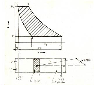
Figure : Cylinder and piston mechanism and p-v diagram of a reciprocating compressor
Work in reciprocating compressor
The p-v diagram reciprocating compressor is shown in figure Along with the skeleton diagram of the cylinder and piston mechanism.
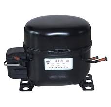
Figure : Reciprocating compressor
When the Piston is in the extreme left position of the inner dead center (IDC), the volume occupied by the gas is Vc=V3 called clearance volume, i.e., the volume between the piston and cylinder head. As the piston moves outward, the clearance gas expands to 4, when pressure inside the cylinder is equal to the pressure at the suction flange of the compressor. As the piston moves further, the suction value S opens and the vapor from the evaporator is sucked in till the extreme right position of the outer dead center (O.D.C) is reached. At this point the volume occupied by the gas is V1. The stroke or swept volume or piston displacement is
Vp= (V1-V3) = (Pi*D2 /4)*L
Where D is the bore or diameter and L is the stroke, i.e., the distance travelled by the piston between I.D.C. and O.D.C. of the cylinder. At 1, the suction value closes as the piston moves inwards and the compression begins. At 2, the pressure in the cylinder is equal to the pressure at the discharge flange of the compressor. A further movement of the piston inward results in the pressure in the cylinder exceeding the condenser pressure. This opens the discharge value D and the vapor from the cylinder flows into the condenser till the piston reaches again the IDC position. Gas equal to the clearance volume Vc remains in the cylinder and the cycle is repeated.
Work in centrifugal compressor
In a steady-flow process, the gas centers the centrifugal compressor, passes over the blades in a centrifugal field and is subjected to momentum change, leaving finally, through a diffuser, at the discharge pressure. From the steady-flow energy equation,
q= (h2-h1) +w
and from the 1st law
q=∑ Tds = ∑(dh-vdp) = (h2-h1)-∑vdp
Comparing the two expressions, we have for work
W= -∑ vdp
It is thus seen that the work of the same for both reciprocating and centrifugal compressors and is given by the expression -∑vdp, integrated between the suction and discharge states. Equation 3.3, therefore, represents the energy equation for both compressors, viz.,
q= (h2-h1)-∑vdp
For an adiabatic compression process, in which q= 0, it gives
w= -∑ vdp = (h2-h1)
Capacity control of centrifugal compressor
Centrifugal compressors require high tip speeds to develop the necessary pressure ratio. The high tip speed is achieved by employing either a large diameter impeller or high rpm or both. Because of large u2, the velocities in general including the flow velocity Cr are high. Also there must be a reasonable width of the shrouds to minimize fiction and achieve high efficiency. Thus, because of the sufficiently large flow area and large flow velocity, the minimum volume that can be handled by a centrifugal compressor is about 50 cubic meters per minute. A single centrifugal compressor, therefore, can be designed for a minimum capacity approximately of 250 TR with R 113 for the purpose of air-conditioning.
The centrifugal compressors are, therefore, used in large capacity installations in which the load varies through a wide range and hence, capacity control in them, although simple, it’s very important.
One of the common methods is by varying the compressor speed through a speed-reduction gear. The decrease in speed results in an operation on a lower head-flow characteristic giving a lower volume flow rate corresponding to the same pressure ratio.
The use of variable inlet whirl vanes is another method of capacity control frequently employed with a constant-speed drive. The capacity is varied by changing the angle at which the gas enters the impeller. The gas then enters with pre rotation and these results in a decrease in flow. Both methods are efficient and the work done remains proportional to the volume handled.
Capacity control of reciprocating compressor
Refrigerating capacity control with reciprocating compressors running at constant speed consists in controlling the quantity of the gas delivered to match the fluctuating load. In an efficient control system the power consumption of the compressor should be proportional to the amount of gas delivered. Various control methods are discussed below.
On and off control
Simple on-off or start-stop control in conjunction with a thermostat is used to advantage in small unitary equipment, such as refrigerators, air conditioners, water coolers, etc. It is particularly suited where there is sudden large demand followed by periods of small or no demand on capacity. Switching off is preferable to running at partial load because of the low part-load efficiency of squirrel-cage induction motors employed in refrigerant compressors.
Holding the valves open
This is the most common method of unloading in multi cylinder V/W compressors. It is accomplished by the lifting of suction valves, usually of two cylinders together, by means of depressors of fingers. The gas drawn in the cylinder during the suction stroke is displaced back into the suction line during the discharge stroke. No work is involved except the frictional work during idling. The depressor rods are operated by a cam which is turned either manually or by means of thermostat or a pressure-stat (for suction pressure). This is the best method of capacity control when the condition is of intermittent unloading that requires idling for short periods only.
More and more cylinders are unloaded, as the suction pressure or evaporator temperature continues to drop, by means of stepped control.
Hot Gas Bypass
In this method, a part of the hot compressed gas is bypassed back to the suction line, through a constant-pressure throttle valve. The valve admits hot gas in the suction line as the evaporator pressure tends to drop, thus maintaining constant suction pressure. This method is not efficient as the suction temperature tends to increase as more and more hot gas is bypassed. The compressor work also tends to increase, thus resulting in the loading of the compressor instead of unloading. However, the method is simple and can be used in conjunction with other methods.
Using Multiple Units
The use of multiple units in reciprocating compressors is very common. Some units may serve the purpose of stand-by equipment as well, thus allowing partial load operation in the case of breakdown of other units.
Construction Features of Reciprocating Compressors
The crankcase is usually of cast iron. Aluminum is also used in small open and welded hermetic compressors. The crankcase encloses the shaft and oil sump and in the case of hermetic units, the motor. The cylinder can be integral with the crankcase or can be in a separate cylinder block. The valves are located in the cylinder head.
Crank-shafts are of forged steel with hardened bearing surfaces, and dynamically balanced. Pistons are usually made of cast iron or aluminum.
Cast irons pistons with a clearance of 0.004 cm/cm of the cylinder diameter would provide for adequate sealing without piston rings. Piston rings are essential with aluminum pistons.
The most crucial parts in reciprocating compressors are suction and discharge valves. Their design should provide for long life and low pressure drops. To minimize the pressure drop, their weight should be small. Reed valves with varying clamping arrangements are commonly employed in refrigeration.
The lubrication systems in refrigerant compressors vary. Both splash and forced feed systems are employed. Shaft seals are used in open-type compressors. Normally stationary seals with bellows are employed. Recently, rotary synthetic seals, tightly fitted to the shaft in a carbon nose, have gained popularly. They are much less expensive.
Features of Centrifugal Compressors
A single-stage centrifugal compressor mainly consists of the following four components
i) An inlet casing to accelerate the fluid to the impeller inlet
ii) An impeller to transfer energy to the fluid in the form of increase in static pressure and kinetic energy
iii) A diffuser to convert the kinetic energy at the impeller outlet into pressure energy (static enthalpy)
iv) A volute casing to collect the fluid and to further convert the kinetic energy into pressure energy (static enthalpy)
Besides this, there are intercoolers, generally integrated with casing, in a multistage compressor. The causing is usually made of cast iron and the impeller, of high speed (chrome-nickel) steels. The maximum stress is developed at the root of the blades.
The diffuser is normally of the vane less type as it permits more efficient part load operation which is quite usual in any air-conditioned plant. A vane diffuser will certainly cause shock losses if the compressor is run at reduced capacity and flow.
Comparison of performance of Reciprocating and Centrifugal Compressors
The advantages of the centrifugal compressor over the reciprocating compressor are high efficiency over a large range of load and a large volume of suction vapor and hence a larger capacity for its size.
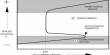
The centrifugal compressor has also many other advantageous features. The most important is the flat-head-capacity characteristic as compared to that of a reciprocating compressor as shown in figure for typical compressors at a constant considering temperature of 38ºC and constant rpm. It is seen that a variation in the evaporator temperature is only 2 to 7.5ºC for a load variation of 100 to 240 TR for a centrifugal compressor, whereas it is -11 to 6ºC for the same load variation for a reciprocating compressor.
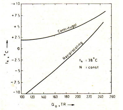
Figure : Nature of capacity variation with evaporator temperature for centrifugal and reciprocating compressors
Another advantageous feature is the non-overloading characteristic as shown in figure. It seen that for a centrifugal machine, there is a decrease in the power requirement with an increase in the condensing temperature. Thus there is no overloading of the motor with increasing condenser temperature. This feature is accompanied by a rapid fall in the flow rate and hence capacity as shown in figure. The power requirement decreases although the horsepower per tons increases. For reciprocating compressors, there is a small increase in the power requirement with an increase in the condensing temperature with consequent overloading of the motor. This is accomplished with a very small decrease in the refrigerating capacity.
The latter aspect of a reciprocating compressor is, however, an advantage so that the capacity of a reciprocating machine is not affected much by an increase in the condensing temperature followed by adverse ambient conditions.
Rotary Compressors
Rotary Compressors are positive displacement, direct drive machines there are essentially tow designs of this compressors:
(i)Rolling piston type
(ii)Rotating vane type.
In the rolling piston type, shown in fig. 6.7, the roller is mounted on as eccentric shaft with a single blade, which is always in contact with the roller by means of a spring.
Where A and B are respectively the diameters of the cylinder and rolling piston and H is the height of the cylinder.
In the rotating vane type, with four vanes, the rotor is concentric with the shaft. The vanes slide within the rotor but keep contact with the cylinder. The assembly of rotor and the vanes is off-center with respect to the cylinder.
In both designs, the whole assembly is enclosed in housing, filled with oil and remains submerged in oil. An oil film forms the seal between the high pressure and low pressure sides. When the compressor stops, this seal is lost and the pressure equalizes.
Rotary compressors have high volumetric efficiencies due to negligible clearance. They are normally used in a single stage up to a capacity of 5TR with R 114. Large rotary compressors are used in low temperature fields, such as the chemical and industrial processing, cold storages and freezing, as high displacement, low stage or booster compressors at -90 to -10ºC evaporator temperatures with R 12, R 22 and ammonia. They are available in 10 to 600 hp sizes with 2 to 120 cubic meters per minute displacement in one unit.
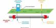
Screw Compressors
Rotary screw compressors also belong to category of positive displacement compressors. The machine essentially consists of two helically-grooved rotors as illustrated in figure which rotate in housing. The male rotor consists of lobes and is normally the driven rotor. The female rotor has gullies and is normally the driven rotor. A four-lobe male rotor will drive a six gully female rotor at two thirds of its speed. At 3600 rpm, the number of compressed gas discharge of a four lobe rotor will be 4×3600= 14,400 per minute.
As in the case of other positive displacement machines, there are three basic continuous phases of the working cycle, viz., suction, compression and discharge.
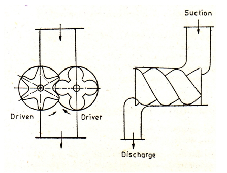
Figure : Sectional and side view of a screw compressor
When the male rotor turns clockwise, an inter lobe space between a pair and housing nearest to the suction end opened and is filled with gas. There are four such pairs to be filled during one revolution in a four lobe and the suction periods overlap one another.
When remising starts, the volume decreases and the pressure rises. The charges is moved helically and compressed until the trapped volume reaches the discharge end. The compression ratio is thus fixed.
Further rotation simply empties the rotor of the high pressure gas until the last traces of the gas are squeezed out, irrespective of the pressure of the condenser.
On completion of the discharge phase, there is no residual gas remaining in the rotors. As a result, there is no expansion of clearance gases. The compressor has no suction and discharge valves.
There are leakage paths in a screw compressor mainly across the line of mesh between the rotors and across the clearance between the rotors and the housing. To eliminate leakage, oil is injected in a number of small jets directed towards the mesh. Oil injection also serves the purpose of cooling and lubricating along with that of sealing the leakage paths.
The rotor profile is patented, the patent rights being held by “Svenska Rotor Maskiner AB”, Sweden.
A slide valve, closely following the shape of the rotors is used for capacity control. At full load the valve is closed. At part load, the valves open enabling a return flow passage to be formed so that a part of the gas drawn into the inter lobe spaces cans flow back to the suction side.
The screw compressor combines many advantageous features of both centrifugal and reciprocating compressors, along with some of its own. As it is a positive displacement machine, high pressure refrigerants, such as R 22 and ammonia are used in it. As it is a high speed rotary machine, a large volume can be handled by it. It is, therefore, found extremely suitable for large capacity low temperature applications such as in food refrigeration.
Like reciprocating compressors, it has no surging problems. It has small pipe dimensions and positive pressures due to the use of high pressures refrigerants. Like centrifugal compressors, it has high compression efficiency, continuous capacity control, unloaded starting and no balancing problems. Also, the compressor is suitable for large capacity installations.