Introduction:
The Microcontroller Based Power Generator Protector (MBPGP) was developed to assist in the selection of relays to protect a generator. The purpose of each relay is described and related to one or more power system configurations. A large number of relays is available to protect for a wide variety of conditions. These relays protect the generator or prime mover from damage. They also protect the external power system or the processes it supplies.
The basic principles offered here apply equally to individual relays and to multifunction numeric packages. The engineer must balance the expense of applying a particular relay against the consequences of losing a generator. The total loss of a generator may not be catastrophic if it represents a small percentage of the investment in an installation. However, the impact on service reliability and upset to loads supplied must be considered. Damage to and loss of product in continuous processes can represent the dominating concern rather than the generator unit.
Accordingly, there is no standard solution based on the MW rating. However, it is rather expected that a 500kW, 480V, standby reciprocating engine will have less protection than a 400MW base load steam turbine unit. One possible common dividing point is that the extra CTs needed for current differential protection are less commonly seen on generators less than 2MVA, generators rated less than 600V, and generators that are never paralleled to other generation.
This guide simplifies the process of selecting relays by describing how to protect against each type of fault or abnormal condition. Then, suggestions are made for what is considered to be minimum protection as a baseline. After establishing the baseline, additional relays, as described in the section on Extended Protection, may be added.
The subjects covered in this guide are as follows:
- Ground Fault
- Phase Fault
- Backup Remote Fault Detection
- Reverse Power
- Loss of Field
- Thermal
- Fuse Loss
- Over-excitation and Over/Under-voltage
- Negative Sequence
- Off-Frequency Operation
- Sync Check and Auto Synchronizing [ Reference-1]
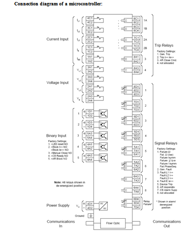
Inputs
The available inputs consist of eight binary inputs (five with the directional over-current option) and nine analog inputs (six without directional over-current option). The binary inputs can be used to receive input such as blocking or breaker failure initiation signals from other protection devices or supervisory control systems. The analog inputs provide connections for both current and voltage inputs. There is a pair of connections for each of the three power phases and neutral for both current and voltage (with directional option). There is one additional analog input for use with a summation CT in high-sensitivity ground fault detection. [Reference-2].
Current Sensing
Current sensing can be selected as either single-phase or three-phase as determined by the style chart. Each current sensing transformer of the relay (1 per phase) receives the output from the (5 A nominal) secondary of a standard system current transformer. Each current sensing input has a sensing range of 0.5 to 12.0 A. The Current transformer ration is 2000:5. The current sensing input burden is less than 0.01VA per input. Two current sensing frequencies are offered: 50 Hz or 60 Hz.
The maximum 1-second current rating is 50 x the maximum tap current selected, or 500 A, whichever is less. For ratings other than those specified by the time curves, the rating is calculated as follows:
I = (50 X tap value or 500 A, whichever is less)
Where, I = Maximum current
T = Time of current flow in seconds
Voltage Sensing
The voltage sensing input transformers receive their input from 120 Volt nominal secondary, standard system voltage transformers. Each voltage sensing input has a continuous voltage ratio of 100:1 VAC, and a sensing input burden greater than 25 K ohms at 120 VAC. Proper directional decisions are assured when the current applied to the relay exceeds 25% of TAP value and the voltage exceeds 1.0 VAC at the setting of the characteristic angle.
Outputs
The outputs consist of three sets of output contacts (relays), two serial data interfaces (one standard, one optional), and a set of eight LED indicators. The first set of output contacts is comprised of eight signal relays – six with both normally open and normally closed contacts and two with normally open contacts only. The second set of output contacts is comprised of four
Command relays intended for tripping protective circuit breakers – two with a double set of normally open contacts and two with single set of normally open contacts. The third set is a device failure relay with both normally open and normally closed contacts.
The first of the serial data interfaces is available through a connector on the front of the operator panel and is intended to be connected to a local personal computer. The second optional serial port is available through the back of the relay housing and is intended for remote communications.
The eight LEDs consist of two dedicated indicators and six programmable indicators. The process of activating the various outputs (LCD, LEDs, output relays) when events occur is referred to as annunciation.
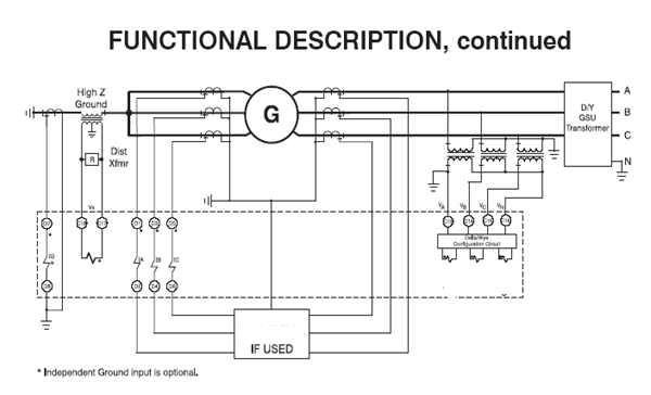
Interfaces to the primary system
The following modular assemblies provide interfacing of the to the power system.
Input transformer
This assembly adjusts the signal levels and provides isolation between the primary system CT and PT circuits and the electronic circuits of the protection. One type of PT and two types of CTs are available, to meet different accuracy and dynamic performance requirements. Space is available for up to 10 transformers, which are selected to suit the application. Up to four assemblies can be used, i.e. 20 inputs.
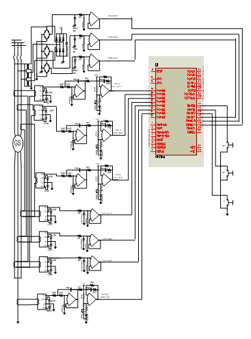
Auxiliary sensing Units
The microcontroller unit received the voltage signal from PTs and current signal from CTs via Hall effect current sensing unit, where develops the operational signal for tripping, alarm and lighting indication signal by following saved schedule programmed in its memory. In this section each current transformer connected with individual Hall Effect current sensing unit which is developed a linear current output signal by following its input. The outputs of hall sensor connected with the microcontroller unit.
System Definition and Constraints
It is realized that one specific technology does not necessarily provide the best answer under all situations. We must therefore limit our discussions to applications within certain constraints. At this time the following broad limits are applicable for the technology under consideration:
The micro or mini turbine systems considered here are in the 100 kW to 500 kW power range. The system comprises mainly of high-speed turbine, generator, controller, protection, and instrumentation.
The Operator Panel
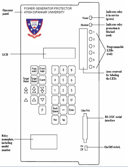
Before programming and operating the relay, you need to be familiar with the keypad and other features of the operator panel. Figure 5-1 provides an illustration of the operator panel for the MBPGP relay. The features, listed below, are described in the rest of this section:
- Keypad
- Display panel
- On/Off switch
- Nameplate
- Light Emitting Diodes (LEDs)
- Reserved area for LED labels
- Serial data port
The operator panel consists of a 28 key membrane keypad and a 32 character alphanumeric display. This panel is used to program the relay and to access stored system data. The keypad provides a standard 10 key numeric section and 18 other control keys. The display is a liquid crystal type (LCD) that provides two lines of 16 characters each.
Keypad
The keys on the operator panel keypad have four basic functions: data entry, navigation, control, and confirmation. The numeric keys are used specifically for data entry or address selection. The navigation keys are used to move around within the address space. The control and confirmation keys are used to accept, reject, or modify configuration options. See Figure 5-1
Display Panel
This 20×4-character liquid crystal display (LCD) is made up of two lines of text, 16 characters each. There are two modes of operation for the display.
- The display mode is the normal operating mode. You can read information, but WE cannot change it. The information that is displayed during normal (i.e., no fault) system conditions is user selectable through the configuration process. Stored event data can be recalled and analyzed in this mode.
- The programming mode is activated by the relay password. The information displayed in this case is configuration data. The relay stays in programming mode until you change and save at least one setting. The normal protective functions of the relay continue to be operational while in programming mode. New settings do not take affect until you exit programming mode.
Note: The LCD is not capable of displaying subscript characters. As a result, lowercase characters, in some cases, are substituted for the subscripts (e.g., IN becomes In and
IEp becomes Iep). In other cases, the subscript is indicated by a dash (e.g., T-REC becomes T-REC). In this manual, specific references to the LCD text will show the symbols as they appear in the display. Otherwise, symbols with correct case and subscripts are used.
on/Off Switch
The On/Off switch controls the operational state of the relay. When the switch is in the “Off” position, the microprocessor is reset and processing stops. Secondary (DC) power output from the power supply module is turned off and the relay failure contact closes. The relay is effectively disabled or blocked in this state. This switch should stay in the “On” position after the relay has been properly installed, programmed, and commissioned. The relay may be turned off for certain maintenance and testing procedures. Refer to the “Maintenance” section for more information on the use of this switch during maintenance. Anytime the On/Off switch is moved from “Off” to “On”, the internal microprocessor is restarted.
Push-buttons
All necessary MBPGP adjustments and inquiries can be carried out from the front of the relay by pressing the respective push-button (9 in total
Nameplate
The nameplate identifies several things about your relay such as rated current and DC supply voltage. The relay model number is printed at the top of the nameplate. The section “Reading the Relay Model Number” in the “Introduction” chapter describes how to interpret the model number.
Light Emitting Diode (LEDs)
Additionally to the display there are lots of LEDs at the front, indicating each of the operational status in the MBPGP. All LEDs are two-colored (red/green) and arranged in two groups:
- System and relay status indications The 15 system indications are arranged underneath the alphanumerical display. They are allocated to a certain function and show:
- Operational voltage available
- Trip
- OFFLINE TEST mode active
- Edit mode active
- Displayed parameter is modified but has not been stored yet
- Switch status of the 5 (optionally 10) output relays
- Display of the relay function (self-test)
- Status display of the 15 digital inputs (if provided) These 15 indications is shown at the left of the display informing about the status of the digital inputs.
The LEDs of MBPGP relay has eight LEDs, six of which can be programmed The LEDs that cannot be changed are as follows:
- Power – Lights up GREEN to indicate the relay is operating properly. Normally this indicator will always be on. This indicator will be off if the On/Off switch is in the “Off” position or if power to the relay is interrupted. It will also be off if the microcontroller monitors function detects a device failure.
- Blocked – Lights up RED to indicate that the relay has detected an internal problem and has “blocked” itself from operation. This indicator will also light briefly during initial power-on and after some settings are changed and saved.
The remaining LEDs (1 through 6) will light up RED to indicate that the event or function assigned to this LED indicator during the configuration process has occurred. These indicators will remain on until reset and the relay will retain this data even if power is lost. Whether or not the indications are retained in the nonvolatile memory is a configuration option. If the indications are not retained, they will be reset when the fault condition is removed. If they are retained, they can be reset locally by the Target Reset key on the operator panel, via a binary input, or automatically when a new fault is detected.
Reserved Area for LED Labels
The MBPGP relay provides a space on the operator panel to label the six LEDs indicating how they are programmed. Labels for the preprogrammed annunciations are provided with the relay. Refer to “Programming the Relay” for instructions on programming the LEDs.
Serial Data Port
The serial data port allows you to connect a personal computer (PC) directly to the relay. This port conforms to the EIA RS-232-C standard. This feature is typically used in conjunction with DIGSIÒ software to quickly retrieve and view event data, program the settings, monitor measured values, and analyze captured waveforms.
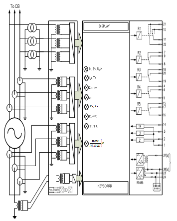
Display
There is provided with a 16-digit, double-line liquid crystal display (LCD), which is of alphanumerical design for an easy dialog. The figure above shows the basic status of the display. Dependent on the mode selected, the following data can be shown on the display:
- Date / Time / Relay type (Home Position)
- Measured operational data
- Measured fault data
- System parameters and protection parameters
- System signals and fault signals
Parameter Interface RS232
At the left of the relay front there is a 9-pole, D-SUB plug-and-socket connector for temporary lap-top connection. At this connection a serial interface RS-232 is provided. A standard IBMTM compatible PC or portable notebook can be connected to this PC interface. To connected MBPGP and PC a 1:1 modem-cable with 9-pole plug-and-socket is used. By using P&P software Microsoft, which is Windows TM compatible, Additionally all measured operational and fault data can be read out of the relay integrated non-volatile memories and the optional fault recorder. [ Reference-2]
Disturbance recorder (optionally)
The right rack place at the relay front is reserved for the disturbance recorder and consists of a duct for the storage medium which is a PC memory card according to the PC card standard (PCMCIA) in this case. This function is proposed for next.
Function Inputs and Signal Inputs (optionally)
These 20 digital inputs (contacts 1-15) are combined on the 16-pole plug-and-socket connector. The sixteenth contact is the common return wire. Any incoming information
- Can direct be assigned to selectable output relays. This application method enables recording of the contact status (open or closed) of external protection devices.
- Can logically be interlinked with MBPGP internal protection functions. The logical inter-linking result can than be assigned to output relays. An input can be considered active when a voltage quantity within the permissible high range is connected to the input contact and the common return wire. If the voltage is lower, the input is classed as being inactive. Digital inputs are galvanical isolated from the relay electronics.
Measuring Inputs
The module consists of six current measuring channels which are used for measuring the three conductor currents of each winding. The CT start point must be formed outside the relay since all 7 CT connections are wired separately on terminals. In addition to other measuring or protection devices the MBPGP can be looped in to existing CT lines, assumed the CT being able to carry the total burden. Apart from further connections for voltage supply of the relay, the module is also provided with a digital input for remote resetting as well as connection facilities for the five output relays.
RESET Input
If a voltage is applied to terminals of the RESET input, the MBPGP is reset to its basic status. By this procedure possible alarms and trip signals are cancelled. The voltage applied for resetting must be within the permissible high-range, although it must not necessarily be identical with the latter.
Alarm Relays
Potential free outputs of the five alarm relays provided are at terminals C, D and E, series 1 to 7. Exact allocation can be taken from the connection diagram. Relay 5 is permanently assigned to Self-test Relay. Function allocation of the remaining relays is free and can be defined when programming. Two of these four relays are provided with two changeover contacts each and the other two with one changeover contact each.
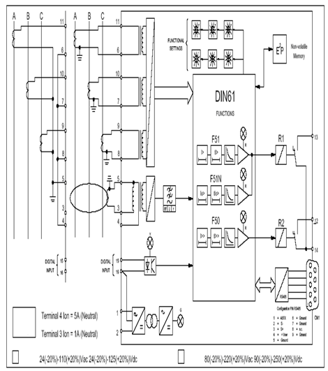
Digital Protection System
The protection system is based on a data bus with digital signal processing for most functions; signal conditioning, analog and digital inputs, A/D conversion, processing and signal output. The components of the system are:
- Static plug-in units, which exchange data via a powerful parallel bus.
- Interfaces to the process (primary system, station equipment), which are isolated from the digital processing unit.
About the Relay
One of the options of MBPGP numerical over-current protection relay is a microprocessor-based, three-phase and neutral relay designed to provide fast, secure and highly reliable over-current protection for high voltage distribution lines. It also provides high-sensitivity ground fault protection, breaker failure protection, bus protection, an automatic re-close function, and optionally, directional over-current protection. It can be used as primary or backup protection on lines, power transformers, generators, motors, and buses. The relay can be mounted in several
types of housing and is easily programmed and operated using the keypad and alphanumeric liquid crystal display (LCD) on the operator panel. The light emitting diodes (LEDs) on the integral operator panel continuously display relay status and target indications. When prompted, the LCD can show operational information such as the relay settings, system conditions, and event data.
The relay can be connected to a PC or to a substation control system, enabling the user to analyze data stored in the relay’s memory and to monitor the relay’s failure (alarm) and status signals.[ Reference-1].
Internal Monitoring and Self-Diagnostics
The relay continuously monitors the operation of its internal hardware and software along with the external CT and VT circuits. Detected failures are logged and the relay is automatically taken out of service. A relay failure signal is available to notify the other parts of the system of this condition.
Measured Values and Event Logging
Measured system current values are available through both the LCD and the serial ports. Operational and fault events are recorded in logs that can be displayed in the LCD or retrieved through the serial ports.
Overview of the Protection Functions
The MBPGP is a numerical protection relay. Numerical protection describes the process of reading analog signals, digitizing them, and then performing all of the measurements, protection functions, comparisons, and trip decision logic mathematically through software or algorithms in the microcontroller. The MBPGP numerical protection allows the same hardware and software components to be used in many different relays. The advantages to the user include:
- Common repair parts
- Consistent user interface
- Field proven software
The following sections describe the protection functions of the MBPGP relay, as listed below:
- Over-current protection
- Directional over-current protection
- Differential Protection
- Phase fault and unbalance phase protection
- High-sensitivity ground fault protection
- Breaker failure protection
- Automatic re-close function
Over-current Protection
Combined over-current & earth-fault relay
- Phase and neutral over-current protection relay for distribution feeders
- Three-phase, high-set and low-set phase over- current protection
- Sensitive non-directional high-set and low-set earth-fault protection
- Integrated circuit-breaker failure protection
- Four standardized Inverse Definite Minimum Time (IDMT) time-current curves as per IEC and BS
- Definite time operation
- Two special-type inverse-time characteristics called RI and RXIDG
- Numerical design for stable time-current curves, high accuracy and reliable operation
- Fault records, event records and diagnostic data can be read remotely via the serial port and locally
- High immunity to electrical interference and robust aluminum case to class IP54
- Improved system reliability supported by a built-in self-supervision system with auto diagnosis
- Serial communication capability for extensive exchange of data between the protection relay and the substation control level
- Powerful optional PC tool for reading, setting and recording relay data and parameters[ Reference-3]
Application
The combined phase and neutral over-current relays are used for the selective short circuit and time over-current protection of radial feeders in distribution networks. The relays are also used for feeder earth-fault protection in isolated neutral networks and networks with resistively earthed neutral. Both the over-current unit and the earth-fault unit feature two stages: a high-set stage and a low-set stage. Further, our new designed relays include an integrated circuit breaker failure protection function. The relays include a local man-machine interface for setting relay parameters and for interrogating measured and recorded parameters.
Design and Principle
The combined over-current and earth-fault relay is a secondary relay to be connected to the current transformers of the protected object. The three-phase over-current unit and the earth-fault unit continuously measure the phase currents and the neutral current of the protected object. On detection of a fault the relay starts, trips the circuit breaker, initiates auto re-closing, provides alarm, records fault data etc. in accordance with the application and the configured relay functions.
When the phase current exceeds the set start current of the low-set stage I>, the over-current unit starts delivering a start signal after a preset ~60 ms start time.
When the set operate time at definite time operation or the calculated operate time at inverse time operation elapses, the over-current unit operates. In the same way the high-set stage I>> of the over-current unit starts delivering a start signal after a preset ~40 ms start time, when the set start current is exceeded. When the set operate time elapses, the over-current unit operates.
When the earth-fault current exceeds the set start current of the low-set stage Io>, the earth-fault unit starts delivering a start signal after a preset ~60 ms start time. When the set operate time at definite time operation or the calculated operate time at inverse time operation elapses, the earth-fault unit operates. In the same way the high-set stage IO>> of the earth-fault unit starts delivering a start signal after a preset
~40 ms start time, when the set start current is exceeded. When the set operate time elapses, the earth-fault unit operates.
The low-set stage of the over-current unit and the low-set stage of the earth-fault unit may be given definite time or inverse definite minimum time (IDMT) characteristic. When the IDMT characteristic is chosen, six time/current curves are available. Four of the curves comply with the BS 142 and IEC 255 and are named “Normal inverse”, “Very inverse”, “Extremely inverse” and “Long-time inverse”. The two additional inverse time curves called the “RI-curve” and the “RXIDG-curve” is also provided.
By appropriate configuration of the output relay matrix, the start signals of the over-current and earth-fault units are obtained as contact functions. The start signals can be used for blocking co-operating protection relays, for signaling and initiating auto re-closing. The relay includes one external binary input, which is controlled by an external control voltage. The function of the control input is determined by selector switches in the protection relay module. The control input can be used for blocking the operation of one or more protection stages, for resetting a latched output relay in the manual reset mode or for enforcing a new set of relay setting parameters by remote control.
[Reference-4 and 2]
Simple arrangement of a Digital Over current Relay
[Reference-2]
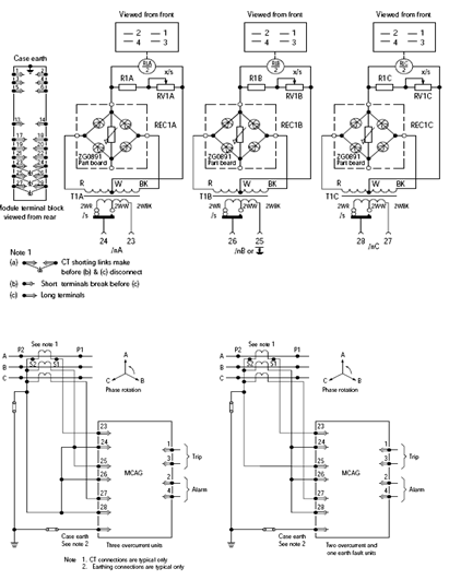
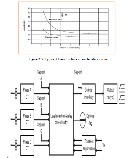
Figure3.4: Coordinate of several relays
Definite time over-current relays offer advantages over inverse time protection in power systems which have a wide variation in source impedance. Faults can be cleared in relatively short times irrespective of the magnitude of the fault current, & coordination of several relays in a system can be obtained at all times regardless of fault current variation.
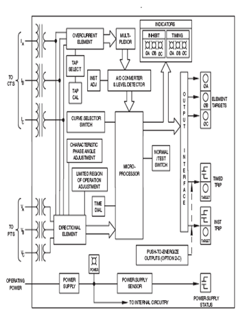
Operation
The over-current relays are available as either a single pole or a three pole unit having an independently adjustable current sensing circuit driving a common adjustable timing element. An instantaneous output operating at either the same current level as the time delay element, or separately adjustable, is available as an option. A timer inhibit Input is also available.
Fully solid state sensing & measuring circuitry is employed with each phase current setting continuously adjustable on a front panel control. High speed, high contact rating output relays are used for increased application flexibility.
The input current transformer & output relay form the essential barriers against high voltage line transients while varistor & capacitor filtering remove auxiliary supply borne noise.
Burden – Auxiliary Supply
Approximately 5 Watt to 15 Watt maximum (dependent on auxiliary voltage, options fitted & condition of output relays).
Operating Time of Instantaneous Element (If Fitted)
Pick up less than 20 ms at 2 x setting. Drop out less than 15 ms when:
- Relay is energized by symmetrical or fully offset current of either polarity, or by three successive applications of fully offset currents of same polarity with time interval of not less than 5 sec between each application. (Current duration of 5 cycles).
- Steady state current magnitudes up to 20 x setting are switched off at or near a current zero with the current prior to switch off being +Ve going, & at or near a current zero with the current prior to switch off being -Ve going. (X/R ratios of the circuit from which the relay is energized lie in the range 10 to 30).
Over-current protection monitors the current levels in the protected power system and compares them with limit values that have been programmed into the relay. When the current levels exceed the programmed limits, appropriate annunciation signals are generated, trip commands are issued, and fault data is recorded. Either of two types of time over-current processing can be selected:
- Definite time (ANSI 51, IEC I>) protection specifies a time delay between the detection of a fault and the output of the trip command. The over-current limit and time delay can be specified separately for phases and neutral. Both normal and high-set protection functions are available. The magnitude of the fundamental frequency is evaluated for this measurement. The time delays can be set to infinity, effectively disabling the function. When the time delay is set to zero, instantaneous over-current protection (ANSI 50, IEC I>>) is implemented.
- Inverse time (ANSI 51, IEC Ip) protection calculates the time delay between fault detection and the trip command as a function of the magnitude of the current. There are three standard IEC inverse time characteristics available for both phase and neutral currents:
- Normal Inverse
- Very Inverse
- Extremely Inverse
A user defined inverse time over-current protection characteristic may also be specified separately for phases and neutral. Additionally, there are two more standard inverse time characteristics available for neutral over-current protection only:
- Long time
- Residual dependent time
When using inverse time protection; either the magnitude of the fundamental frequency or the true rms value can be evaluated for the measurement. A time multiplier may be programmed to shift the selected characteristic in time. The multiplier may be set to infinity, effectively disabling the protection element. [Reference-2].
Directional Over-current Protection (Optional)
An optional feature available on the MBPGP relay is the ability to determine the direction of over-current faults relative to the position of the relay in the system. With the exception of the high-set element, additional directional definite or inverse time over-current protection elements can be implemented. They can be set to respond to faults in either the forward or reverse directions. The definition of forward and reverse current flow is also programmable. When directional over-current protection is used, the non-directional elements are still available. Inverse time characteristic selection or trip time delays are separately programmable for the directional over-current protection elements for both phases and neutral. The pickup values for the directional over-current elements are the same as for the non-directional elements.
High-Sensitivity Ground Fault Protection
The high-sensitivity ground fault protection element functions independently of the over-current protection elements. It is intended primarily for detecting ground fault conditions under which the resulting ground currents are relatively small. For isolated or compensated system, this protection function picks up on excessive displacement voltage. The direction of the ground fault can also be determined. If the directional over-current option is installed, an indication of the faulted phase is also available.
Breaker Failure Protection
When a fault is detected and a trip command is issued, the relay will continue to monitor the currents anticipating removal of the fault. If, after a specified time delay, the circuit breaker that was the target of the trip command fails to remove the fault, the relay can signal another part of the system to attempt fault removal. The timeout for this protection can be programmed. Breaker failure protection may also be initiated externally by means of a binary input signal.
Automatic Re-close Function
In many cases, faults on transmission and distribution lines are of a temporary nature. In situations of this type, it is desirable to attempt restoration of service by automatically re-closing the circuit breakers after a reasonable time delay. The MBPGP relay provides a complete and comprehensive automatic re-close (AR) function that includes the following:
- On/Off control
- Single and multi-shot three-pole re-close.
- Selection of which protection elements can initiate AR.
- Individually programmable rapid (RAR), delayed (DAR), and final (END) AR trip delay times for over-current and high-sensitivity ground fault protection elements.
- Programmable number of additional shots (DAR) after the initial shot (RAR) for phases and neutral.
- Individually programmable rapid and delayed action times.
- Individually programmable rapid and delayed dead times for phases and neutral.
- Programmable reclaim time after
- successful AR cycle
- unsuccessful AR cycle
- manual re-close of circuit breaker
- Blocking of AR
- Following manual re-close.
- on reverse direction fault detection (with directional over-current option)
- if high-set over-current protection picks-up during RAR or DAR dead time.
Block diagram:
Programming the Relay
Before operating the MBPGP relay, you must program it specifically for your system. This chapter tells you how to:
- Use the operator panel
- Place the relay in programming mode
- Program the relay
- Save new settings
This chapter also identifies the factory presetting for the power system, protection functions, and relay configuration settings. Setting options and ranges are included. Before you begin any procedure in this chapter, either fill out the worksheets provided in the “Setting Worksheets” section of this manual or obtain a copy of the worksheets as completed by a relay engineer. To avoid operating problems due to incorrect parameters, the relay should be configured as soon as possible after the installation procedures are completed. If present, remove the protective cover to access the operator panel. Be sure that the On/Off power switch is in the “On” position and the Power LED is on.
General Procedures for Programming the Relay
To program the relay, you must first change the relay from display to programming mode and choose the address block or number having the setting(s) you need to change. Once you are in programming mode, you can change any settings in any address block. The procedures and tables given throughout this chapter identify the settings that require a numeric value within a specified range and the settings that are selected from a list of options.
This section tells you how to do the following operations as part of the programming process:
- Change to programming mode
- Select an address block
- Program a selectable setting
- Program a numeric setting
Generator differential protection
Term | Explanation | |
ID | Bias current | This is the current passing through the generator from the star point side to the grid side. This current is representing the normal load. |
Id | Differential current | The difference between grid side current and star point side current of one winding. |
Ia | Pickup current | If differential current exceeds the pickup current, the relay trips. |
| Fault Current due to operational condition | This kind of fault current is the component of the measured differential current which. However, is not caused by a fault of the object to be protected but is of systematic nature. |
| Stabilization | Under this heading all measures are compiled which stabilize the differential relay against nuisance tripping. Stabilizing always means the pickup current is raised and by this the differential relay becomes more insensitive, but is never completely blocked. |
IS | Stabilizing current | This current develops from the bias current and represents the extent of stabilizing measures necessary as result of the fundamental analysis. Parameters of the pickup characteristic can be set. |
| Pickup characteristics | This characteristic defines the stabilizing current dependence on the pickup current. |
Flowchart of the Power Generator Protector
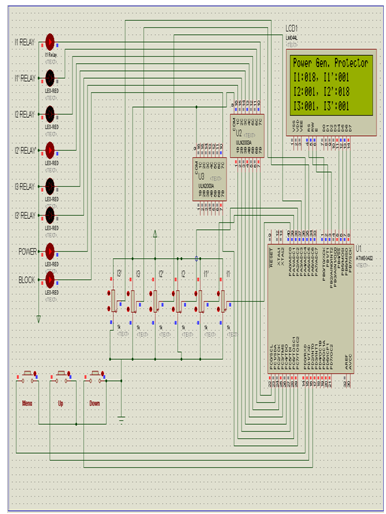
Simulated Diagram:
Reference:
1.http://www. google.com.
2.http://www.wikipedia.org/w/index.php?title=Special%3ASearch&redirs=0&search=Operating+Time+of+Instantaneous+Element+%28If+Fitted%29&fulltext
3. P. K. Dash, O. P. Malik, and G. S. Hope, “Digital differential protection of a generating unit scheme and real-time test results,” IEEE Transactions on Power Apparatus and Systems, vol. PAS-96, no. 2, March/April 1977.
4. H. Tao and I. F. Morrison, “Digital winding protection for large generators,” J. Electr. Electron. Eng. Aust., 3 (1983), 316-321.]