Introduction:
Renewable energy is a field of science that has gained a lot of research over the last few decades. Due to climate change and the scarcity of raw materials, scientists are now looking for new ways in which they can produce energy that is safe, cheap, easy to implement, feasible and is environment- friendly.
In the last decade and a half, Bangladesh has struggled with load-shedding; this is mainly due to a large increase in the consumption of electricity and a failure to meet those demands by the generating stations. As time has moved on, some people have worked on minimizing the load-shedding problem, by means of installing IPS (Instant Power Supply). Though it is efficient, it is very expensive to maintain and has a small lifespan. That is why it is better to seek an alternative.
In order to find a solution to the problem, we have designed a wind turbine, a technology that is environment-friendly. We have used a simple mechanical gear system that can be either used for the purposes of hydro or wind turbine. The same gear principle is used to produce electricity simply from the rotation of the blades. The dc current produced is stored in a small battery and it can be used to light up a bulb or used to power AC appliances after conversion through an inverter during power failure. This is more economical as it is cheap, takes up less space, easy to install, and is very easy to maintain.
Background:
Wind power has been used from the time sailors sailed dependent on the direction of wind up to modern day. Wind power has been used for many purposes which have varied in shapes and sizes for operations throughout the history of human civilization.
With the development of electric power, wind generators have also changed in the way they are used in order to produce electricity .Through out the 20th century small wind plants where set up in the form of wind farms, supplying power to the grid or stand-alone systems which were used for small residences.
In early Babylon a simple mechanical wind turbine was used known as Hero’s wind powered-organ. This was mainly use to ventilate air for a room. A wind-driven wheel was the prayer wheel, which was used in ancient Tibet and China since the 4th century. In 1st century AD the wind wheel was the first of its kind that was actually used to power a machine using a wind driven wheel.
The first practical windmill was built in the early 7th-9th century in Sistan, a region near Iran and Afghanistan. Windmills were widespread over Middle East and Central Asia. The first windmills appeared in Europe dating in the 12th century. In addition, windmills, unlike water mills, were not rendered inoperable by the freezing of water in the winter.
Around the 18th century windmills were used to pump water for salt making on the island of Bermuda, and on Cape Cod during the American revolution.
In the early 1900’s wind turbines were used on ships as an alternative source of saving energy for an emergency such as sailing ship “Chance”, New Zealand, 1902.
In Denmark by 1900 there were about 2500 windmills for mechanical loads such as pumps and mills, producing an estimated combined peak power of about 30 MW.
In the American mid-west between 1850 and 1900, a large number, perhaps six million, small windmills were installed on farms to operate irrigation pumps.
The first windmill for electricity production was built in Scotland in July 1887 by Prof James Blyth of Anderson’s College, Glasgow (the precursor of Strathclyde University).he used this on his holiday cottage at Marykirk in Kincardineshire and was used to charge using accumulators, lighting the cottage, thus making it the first house in the world to have its electricity powered by wind energy. His invention provided a large amount of energy that could power the lighting for the main street.
Development in the 20th century might be usefully divided into the periods:
- From 1900 to 1973, this was during a time when wind farms where competing against fossil fuel plants centrally-generated electricity.
- 1973-onward, when the oil price crisis spurred, the search for non-petroleum energy sources began.
In Denmark, wind power was very important, producing electricity over a wide area rather than confining it to a single power-plant. The Danish wind power development improved significantly in terms of large increase in turbine efficiency and improvements in storage capacity. Thus began a large production of turbines.
In the late 1920’s the brothers Joe Jacobs and Marcellus Jacobs opened a factory, Jacobs Wind in Minneapolis to produce wind turbine generators for farm use. Their turbines had simple operations to produce and store electricity. Many other manufacturers produced small wind turbine sets for the same market, including companies called Wincharger, Miller Airlite, Universal Aeroelectric, Paris-Dunn, Airline and Winpower.
By the 1930s, windmills were quite common among people that could not have electricity distributed to them. These were used to generate electricity so that it can be later stored in a battery. These machines had the capability to generate about few hundred watts to several kilowatts. They were not just providing power for farms, but they were also used for isolated applications such as electrifying a bridge structure to prevent corrosion. In this period, high tensile steel was cheap, and windmills were placed atop prefabricated open steel lattice towers.
In 1941, the world’s first megawatt-size wind turbine was connected to the local electrical distribution system on the mountain known as Grandpa’s Knob in Castleton, Vermont, USA. It was designed by Palmer Cosslett Putnam and manufactured by the S. Morgan Smith Company. This 1.25 MW Smith-Putnam turbine was successful for 1100 hours until a blade failed at a known weak point, which had not been reinforced due to war-time material shortages.
During World War II, German U-boats used to recharge their batteries by using a supply from light houses that had small wind generators of the island of Insel Neuwerk. This had a capacity of around 18 kW. This was later changed after 20 years when underground cable lines were used.
From the mid 1970’s through the mid 1980’s the United States government decided to advance the technology and enable large commercial wind turbines. This effort was led by NASA at the Lewis research center in Cleveland, Ohio and was a great step towards successful government research and development activity.
They led to more research on, including: steel tube towers, variable-speed generators, composite blade materials, partial-span pitch control, as well as aerodynamic, structural, and acoustic engineering design capabilities. The Mod-2 wind turbine cluster produced a total of 7.5 megawatt of power in 1981. In 1987, the Mod-5B was the largest single wind turbine operating in the world with a rated power of 3.2 megawatts. It demonstrated an availability of 95 percent, an unparalleled level for a new first-unit wind turbine.
Later, in the 1980s, California provided tax rebates for wind power. These rebates funded the first major use of wind power for utility electricity. These machines, gathered in large wind parks such as at Altamont Pass would be considered small and un-economic by modern wind power development standards.
In the mid 1970’s people wanted to have a more self sufficient life style and people invested more in windmills because they were a lot cheaper and solar cells were less cost effective on a small scale . Most people found out that reliable wind generators were a lot more complex engineering project.
All major horizontal axis turbines today rotate the same way (clockwise) to present a coherent view. However, early turbines rotated counter-clockwise like the old windmills, but a shift occurred from 1978 and on.
In the 1990s, as aesthetics and durability became more important, turbines were placed atop tubular steel or reinforced concrete towers. Small generators were connected to the tower on the ground, and then the tower was raised into position. Larger generators were hoisted into position atop the tower and there was a ladder or staircase inside the tower to allow technicians to reach and maintain the generator, while protected from the weather.
The most common turbines that were used were two-bladed horizontal-axis machines. Those had a peak output of 200 watts. Later on, more capital investment was made for funding wind turbines since network power distribution provided farms with more dependable usable energy.
During the beginning of the 21st century, there has been a huge concern regarding the use of fossil fuels as it played a major issue when it came towards the environment. With countries adjusting to combating climate change and global warming, the shift to renewable energy has become an important issue. There has been rapid growth in the production of wind turbines. Even though wind generators produce electricity they still fail to compare to fossil fuels. There is a large fear that one-day fossil fuels will end and hence an urgency to expand to wind power.
Objective of this work:
As climate change and global warming has become such a major issue, being environment friendly plays a key role for the future especially when it comes to producing energy. Countries are looking into ways on how to reduce their carbon footprint through the use of renewable energy. Wind energy is found naturally and is abundant. Looking towards nature to produce energy is needed in order to power future homes and countries. Our objective of our work is simply to create a full fledged practical solution to renewable energy where it can be used where there is low wind flow.
Introduction to this Thesis:
In Chapter 1, a brief introduction to the entire project is given along with some historical background on wind energy.
Chapter 2 focuses mainly on the wind turbine blades, the orientation, and blade composition. Advantaged and Disadvantages of the HAWT and VAWT turbines are discussed in detail.
Chapter 3 deals with some of the physical characteristics and coefficients involved such as solidity, performance coefficient and tip speed ratio. The Tower structure and wind regime are also discussed.
Chapter 4 shows the power calculations involved with the final electrical power extracted from wind.
The gear system for our project is discussed thoroughly in Chapter 5 along with the originally intended concept and the final design.
Various generating units are considered for the wind generator in Chapter 6.
Chapter 7 covers the role of the inverter in detail. Modern inverters and their key features are discussed along with their utilization in the wind energy systems of today.
The basic circuit components of an inverter are covered in Chapter 8.
Finally, the conclusions of our research are in Chapter 9.
Wind turbine:
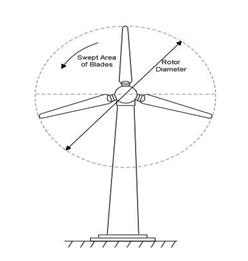
Over view:
A wind turbine is a rotary device which uses wind energy to convert mechanical energy to electrical energy by the means of blades.
A wind generator is a device that generates electrical power from wind energy.
Wind generators have traditionally been wind turbines, i.e. a propeller attached to an electric generator attached to appropriate electronics to attach it to the electrical grid or to charge batteries.
Types of wind turbine:
Wind turbines are generally categorized into two classes based on the orientation of the rotor
- Vertical Axis wind turbine (VAWT)
- Horizontal Axis wind turbine (HAWT)
Vertical Axis wind turbine (VAWT):
The vertical axis wind turbine has its main rotor shaft arranged vertically. The generator and gearbox can be placed near the ground, so the tower doesn’t need to support it.
The benefit of using such an arrangement is that the turbine does not need to be pointed into the wind to be effective. This is an advantage on sites where the wind direction is highly variable. Some designs of VAWT produce pulsating torque.
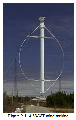
It is difficult to mount vertical-axis turbines on towers, meaning they are often installed nearer to the base on which they rest, such as the ground or a building rooftop. The wind speed is slower at a lower altitude, so less wind energy is available for a given size turbine. Air flow near the ground and other objects can create turbulent flow, which can introduce issues of vibration, including noise and bearing wear which may increase the maintenance required to decrease the service life.
However, when a turbine is mounted on a rooftop, the building generally redirects wind over the roof and these can double the wind speed at the turbine. If the height of the rooftop mounted turbine tower is approximately 50% of the building height, this is near the optimum for maximum wind energy and minimum wind turbulence.
Advantages | Disadvantages | ||
| 1) A massive tower structure is less frequently used, as VAWTs are more frequently mounted with the lower bearing mounted near the ground. | 1) A VAWT that uses guy-wires to hold it in place puts stress on the bottom bearing as all the weight of the rotor is on the bearing. Guy wires attached to the top bearing increase downward thrust in wind gusts. Solving this problem requires a superstructure to hold a top bearing in place to eliminate the downward thrusts of gust events in guy wired models. | ||
| 2) Designs without yaw mechanisms are possible with fixed pitch rotor designs. | 2) The stress in each blade due to wind loading changes sign twice during each revolution as the apparent wind direction moves through 360 degrees. This reversal of the stress increases the likelihood of blade failure by fatigue. | ||
| 3) The generator of a VAWT can be located nearer the ground, making it easier to maintain the moving parts. | 3) While VAWTs’ components are located on the ground, they are also located under the weight of the structure above it, which can make changing out parts very difficult if the structure is not designed properly. | ||
| 4) VAWTs have lower wind startup speeds than HAWTs. Typically, they start creating electricity at 6 m.p.h. (10 km/h). | 4) Having rotors located close to the ground where wind speeds are lower due to the ground’s surface drag, VAWTs may not produce as much energy at a given site as a HAWT with the same footprint or height. | ||
| 5) VAWTs may be built at locations where taller structures are prohibited. | |||
| 6) VAWTs situated close to the ground can take advantage of locations where mesas, hilltops, ridgelines, and passes funnel the wind and increase wind velocity. | |||
| 7) VAWTs may have a lower noise signature. | |||
| 8) Multiple VAWTs may be arranged in counter-rotating configurations so as to extract energy from the wakes of adjacent wind turbines allowing for greater power densities. |
Horizontal axis wind turbine (HAWT):
Horizontal-axis wind turbines (HAWT) have the main rotor shaft and electrical generator at the top of a tower, and must be pointed into the wind. Small turbines are pointed by a simple wind vane, while large turbines generally use a wind sensor coupled with a servomotor. Most have a gearbox, which turns the slow rotation of the blades into a quicker rotation that is more suitable to drive an electrical generator.
Turbine blades are made to be stiff so to prevent the blades from being pushed into the tower by high winds. Additionally, the blades are placed at a considerable distance in front of the tower and are sometimes tilted forward into the wind by a small amount.
Downwind machines have been built, despite the problem of turbulence (mast wake), because they don’t need an additional mechanism for keeping them in line with the wind, and because in high winds the blades can be allowed to bend which reduces their swept area and thus their wind resistance. Since cyclical (that is repetitive) turbulence may lead to fatigue failures, most HAWTs are of upwind design.
Horizontal axis wind turbine blades never move downwind, so they can get no help from drag forces. Instead they use lift.
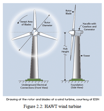
Figure 2.2: HAWT wind turbine
| Advantages | Disadvantages |
| 1) Variable blade pitch, which gives the turbine blades the optimum angle of attack. Allowing the angle of attack to be remotely adjusted gives greater control, so the turbine collects the maximum amount of wind energy for the time of day and season. | 1) The tall towers and blades up to 45 meters long are difficult to transport. Transportation can now amount to 20% of equipment costs.
|
| 2) The tall tower base allows access to stronger wind in sites with wind shear. | 2) Tall HAWTs are difficult to install, needing very tall and expensive cranes and skilled operators. |
| 3) High efficiency, since the blades always move perpendicular to the wind, receiving power through the whole rotation. In contrast, all vertical axis wind turbines, and most proposed airborne wind turbine designs, involve various types of reciprocating actions, requiring airfoil surfaces to backtrack against the wind for part of the cycle. Backtracking against the wind leads to inherently lower efficiency. | 3) Massive tower construction is required to support the heavy blades, gearbox, and generator.
|
| 4) The face of a horizontal axis blade is struck by the wind at a consistent angle regardless of the position in its rotation. This results in a consistent lateral wind loading over the course of a rotation, reducing vibration and audible noise coupled to the tower or mount. | 4) Reflections from tall HAWTs may affect side lobes of radar installations creating signal clutter, although filtering can suppress it.
|
| 5) Their height makes them obtrusively visible across large areas, disrupting the appearance of the landscape and sometimes creating local opposition. | |
| 6) Downwind variants suffer from fatigue and structural failure caused by turbulence when a blade passes through the tower’s wind shadow (for this reason, the majority of HAWTs use an upwind design, with the rotor facing the wind in front of the tower).
| |
| 7) HAWTs require an additional yaw control mechanism to turn the blades and nacelle toward the wind. | |
| 8) In order to minimize fatigue loads due to wake turbulence, wind turbines are usually sited a distance of 5 rotor diameters away from each other, but the spacing depends on the manufacturer and the turbine model. |
Blade Composition:
| Material | Types | Characteristics |
| Metal | Steel | Heavy and expensive |
| Aluminum | Lighter and easy to work with | |
| Expensive | ||
| Subject to metal fatigue | ||
| Wood | Solid plank | Strong, light-weight, cheap, abundant, flexible |
| Laminates | ||
| Veneers | ||
| Composites | ||
| Fiberglass | Glass fiber and epoxy composites | Lightweight, strong, inexpensive, good fatigue characteristics |
Variety of manufacturing processes
|
Twist and Taper:
When a blade rotates, each point on it travels at a different speed. Thus, the further it is away from the root, the higher the velocity. This means that the contribution to lift and drag of every point on the blade differs, with each aspect getting larger when moving closer to the rotor tip. To change this distribution, blades are twisted and, sometimes, also tapered.
The twist is such that the angle of attack increases when travelling towards the root, producing more lift. Tapering the blade also contributes to achieving a more evenly spaced lift distribution. With blade tapering, the blade’s surface gets larger when travelling towards its root.
Blade twists and taper leads to large angles of attack and large blade surfaces at the root. However, close to the root, the blade is traveling over the hull, so the generated downwash does not contribute to helicopter thrust. For this reason, rotor blades are often cut out near the root. Another reason for rotor blade cut out is to reduce the effects of potential reverse flow (on the retreating rotor blade) when flying at high speeds.
Number of blades:
When designing a wind turbine, the number of blades plays a key role when it comes to efficiency of designing a wind power system. Normally the number of blades varies from using one blade or two or three blades.
Features of using one blade:
When using one blade, the rotor must move more rapidly to capture the same amount of wind to generate the same power if the number of blades where increased. In turn this reduces the gearbox ratio and adds weight of counterbalance which negates some benefits of lighter design.
Figure 2.3: A single blade HAWT turbine
The blades are easier to install because the entire rotor can be assembled on ground. Some of the disadvantages of using one blade design is the higher speed means more noise, visual and wildlife impacts. It captures 10% less energy than two blade design and does not provide any cost savings.
Features of using two blades:
The two blade design has the same advantages and disadvantages of the one blade design. One of the necessary requirements when using two blade turbines is the need of teetering the hub or shock absorbers because of the gyroscopic imbalances. It also captures 5% less energy than that of the three blade design.
Features of using three blades:
The angle between each blade creates a perfect balance causing balance of gyroscopic forces along the blades. As a result it creates a slower rotation. Some of the advantages of using three blade turbines that it increases gearbox and transmission costs. It is more aesthetic and produces less noise. Lastly it causes lesser bird strikes.
Factors of wind turbine:
Betz’ theory:
In order to calculate the power of the wind, Betz theory can be used. Assuming that the rotor is ideal, that is to say, it has no hub and has an infinite number of blades which in turn offers no resistance where the drag to the passage of air through it is negligible. Thus it is a pure energy converter. Moreover, the conditions over which the whole swept area by the rotor is supposed to be uniform and the air through and beyond the rotor is assumed to be axial.
Formula for the maximum power of the wind = ½ρAV3
where,
ρ is the air density,
A is the swept area,
V is the wind speed.
This expression constitutes Betz’ formula.
Betz’ limit:
All wind power cannot be captured by rotor or air would be completely still behind rotor and will not allow more wind to pass through.
The theoretical limit of rotor efficiency is 59%. Although most modern wind turbines have an efficiency of the 35 – 45%.
Drag and Lift:
When the wind is blowing through some object, it exerts two types of force, lift and drag.
Drag is the force of wind pushing straight downwind. It is parallel to the direction of motion. In order to increase turbine efficiency the drag force must be small.
Lift force is perpendicular to the direction of motion. This force must be large so that blade rotates.
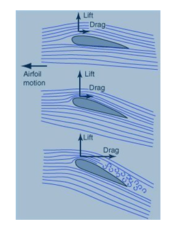
The relative sizes of the drag and lift forces depends on the shape of the object. Good airfoils can have lift 30 times greater than drag.
Pitch:
The blades of a rotor are curved in such a way that they deflect the wind. The lift force created causes the rotor to rotate. In order to generate the maximum amount of lift, blades must be set at an appropriate angle to the wind; this angle is called the pitch.
Solidity:
Solidity is the percentage of the circumference of the rotor which is filled by the blades.
Solidity (%) = (31.8 x number of the blades x blade width)/rotor diameter.
The greater the solidity of a rotor the slower it needs to turn to intercept the wind. There are some factors that need to be known:
- Low solidity: high speed, low torque.
- High solidity: high torque, low speed.
Tip speed ratio:
This is the ratio of the speed of the blade tips to the speed of the wind.
Tip speed ratio = (0.052 x rotor diameter x rotational speed in rpm)/wind speed
If the rotor is rotating faster than the wind speed, it will have a tip speed ratio of greater than one.
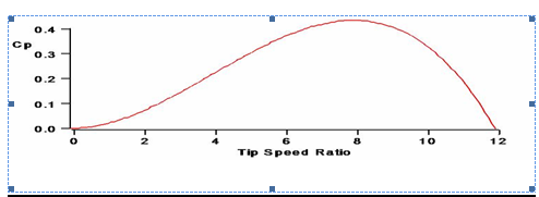
Performance coefficient:
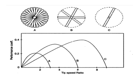
The performance coefficient of a rotor is the fraction of wind energy passing through the rotor disc which is converted into shaft power. This is actually a measure of the efficiency of the rotor and it varies with the tip speed ratio. Typical performance coefficient verses tip speed ratio curves for rotors of varying solidity are shown in figure below.
Torque:
Torque is the turning force produced by the rotor. It depends on the solidity and tip speed ratio of the rotor. High solidity rotors with low tip speed ratios produce much more torque than low solidity, high speed rotors. The figure mentioned illustrates this.
Towers:
Normally a wind tower consists of the turbine and the nacelle which contains the mechanical gear, the electrical generator, the yaw mechanism, and the stall control.
The height of a tower in the past has been in the 20 to 50 meter range. For medium and large size turbines, the tower is slightly taller than the rotor diameter. Small turbines are generally mounted on the tower a few rotor diameters high. Both steel and concrete towers are available and are being used. The construction can be tubular or lattice.
The main issue in the tower design is the structural dynamics. The tower vibrations and the resulting fatigue cycles under wind speed fluctuation are avoided during designing the wind turbine. This requires careful avoidance of all resonance frequencies of the tower, the rotor and the nacelle from the wind fluctuation frequencies.
The greater the height of the tower, the stronger the towers must be to endure the forces of the wind. This is because of the tendency of a tall structure to bend and as the height from the ground increases so does the wind speed.
Also the greater the size and weight of the rotor or the gear system the stronger the tower must be.
Wind regime:
To determine the size of a wind turbine so that it provides sufficient electricity and runs efficiently in the local wind condition, one or a combination of the following methods should be used:
- Wind measurement at proposed wind turbine site.
- Install a wind turbine and adjust it to suit the wind regime if necessary.
- Infer the wind speeds from nearby site data.
The wind regime parameters needed:
Ideally the following parameters should be measured:
- Average annual wind speed.
- Average monthly wind speed for each month.
- Typical diurnal wind speed pattern for each month.
- Length and annual distribution of lull periods.
- Maximum gust wind speed.
- Wind direction.
In practice it may not be possible to obtain numerical data for all of these. In particular estimates of (4) and (5) may have to be made based on discussions with local inhabitants.
Maintenance:
The efficiency, economy, safety and length of service of any piece of equipment will be proportional to the standard of maintenance. Wind turbines require only a little or no maintenance; however little the maintenance is, it is still important.
Rotor Blade Airfoil:
The efficiency of fast turning wind rotors are determined greatly by the aerodynamic properties of the airfoils used. The most important parameter for the airfoil is characterized by the lift to drag ratio. (L/D)
Low speed rotors need many blades but their airfoil characteristics are not so important. High speed rotors manage alright with fewer blades, but their airfoil characteristics become a decisive factor for power generation.
‘Hollow’ metal blades may start up in very low wind speeds, but there is no power at such low wind speeds. Hollow airfoils start up in low wind speeds, but they also stall faster, make noise, lose power and will not spin correctly in solid winds, so potential for obtaining power from the middle and top end of the power band is limited.
If the target is to get a decent power output in light winds, then metal hollow foils would do the job. They are cheap and are likely to work well at speeds up to 15 mph. Not much power is obtained, but at least we are getting some power at least.
In countries like Bangladesh, where steady wind flow areas are unlikely to have wind speeds higher than 15 mph, the hollow foil seems like the most feasible option.
However, from a global perspective, considering strong wind flows as well as moderate winds, then it’s actually far more efficient to use a better airfoil. A good power band is obtained without the noise, and when winds are light, power comparable to hollow airfoils is still obtained anyway.
The best blades are a full foil shape, as recommended by NASA and used in professional Wind Generators. A full foil has a curved top and a rather flat ‘belly’. This shape will not stall as soon as the hollow foils and provides much more power throughout a wider power band.
Power Extracted from the Wind:
Kinetic Energy:
Kinetic energy (Ek) of a stream of air with mass (m) and velocity (V) is given by
(1)The kinetic energy of the air stream available for a turbine with a wind rotor of cross-sectional area is expressed as
(2)where v is the volume of air available to the rotor and ρa is the density of air.
Mechanical Power:
The air interacting with the rotor per unit time has a cross-sectional area equal to the cross-sectional area of the rotor (AT) and the thickness equal to the wind velocity (V). Therefore, the mechanical power (energy per unit time) coming in the upstream wind is given by
(3)It can be seen that air density, area of the wind rotor, and the wind velocity are factors that influence the power generated from a wind turbine. Wind velocity is the most dominant factor because of its cubic relationship with power.
The density of air can be affected by temperature, atmospheric pressure, air components, and elevation. Dry air can be assumed as an ideal gas. The ideal gas law is expressed as
(4)where p is the pressure, VG is the gas volume, n is the number of kilo-moles of gas, T is the temperature, and R is the universal gas constant. Density of air is the ratio of the mass of 1 kilo mole of air to its density. This is shown by
(5)Combining the two equations 4 and 5 gives
(6)If the elevation and temperature are known, given by the variables Z and T respectively, then the air density can be calculated by(7)Equation 7 shows that as size elevation and temperature increase, the density of air will decrease. Due to the low density of air, large sized turbines are often required to produce a substantial amount of power.
Specific Power:
The actual power extracted by the rotor blades can be calculated by taking the difference between the upstream and downstream wind powers. The power in the upstream wind, also referred to as the power density, is given by
Specific Power of the Site (8)
where Va is the velocity of air.
The rotor blades are not able to extract all of the upstream wind power. Therefore, some power is left in the downstream air that moves past the turbine at a reduced speed. The upstream velocity is the velocity of the wind at the entrance of the rotor blades, and the downstream velocity is the velocity of the wind at the exit of the rotor blades. The equation to determine the mechanical power extracted by the rotor is expressed as
Wind power:
The terms inside the brackets of equation represent the mass flow rate of air through the turbine’s rotating blades. The variables VU and VD represent the upstream and downstream velocities, respectively. This equation can be rearranged in the following form
(10)If the variable Cp represents , then the power extracted by the blades can
be expressed as a fraction of the upstream wind power by
(11)Cp is called the power coefficient of the rotor or rotor efficiency, and represents the fraction of the upstream wind power that is extracted by the rotor blades and fed to the generator. The power remaining is dissipated in the downstream wind. The theoretical maximum rotor efficiency occurs at 0.59 when the ratio is equal to one third. Under this condition,
Pmax (12)The Cp value is often expressed as a function of rotor tip-speed ratio (TSR), which is defined as the linear speed of the rotor’s outermost tip to the upstream wind speed. If the value of 0.5 is assumed as the practical maximum rotor efficiency for modern high-speed two-blade turbines, the maximum power output the turbine is
Pmax (13)
Gear System:
A gear is a rotating machine part having cut teeth, or cogs, which mesh with another toothed part in order to transmit torque. Two or more gears working in tandem are called a transmission and can produce a mechanical advantage through a gear ratio and thus may be considered a simple machine.
Function and advantage of using gear system:
A gear is a component within a transmission device that transmits rotational force to another gear or device. A gear is different from a pulley in that a gear is a round wheel which has linkages, “teeth,” that mesh with other gear teeth, allowing force to be fully transferred without slippage.
Depending on their construction and arrangement, geared devices can transmit forces at different speeds, torques, or in a different direction, from the power source. The most common situation is for a gear to mesh with another gear, but a gear can mesh with any device having compatible teeth, such as other rotational gears, or linear moving racks.
A gear’s most important feature is that gears of unequal sizes (diameters) can be combined to produce a mechanical advantage, so that the rotational speed and torque of the second gear are different from that of the first.
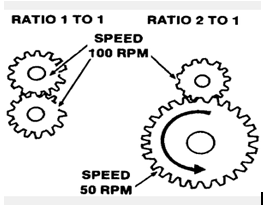
The interlocking of the teeth in a pair of meshing gears means that their circumferences necessarily move at the same rate of linear motion. Since rotational speed is proportional to a wheel’s circumferential speed divided by its radius, we see that the larger the radius of a gear, the slower will be its rotational speed, when meshed with a gear of given size and speed. The same conclusion can also be reached by a different analytical process: counting teeth. Since the teeth of two meshing gears are locked in a one to one correspondence, when all of the teeth of the smaller gear have passed the point where the gears meet, when the smaller gear has made one revolution – not all of the teeth of the larger gear will have passed that point. The larger gear will have made less than one revolution.
In essence a gear with half the diameter of the gear it is meshed to will rotate with twice the speed.
D2/D1 = V1/V2
Spur Gears:
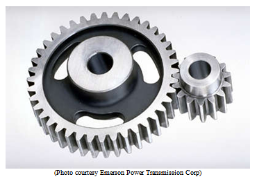
Spur gears are the most common type of gears. They have straight teeth, and are mounted on parallel shafts. Sometimes, many spur gears are used at once to create very large gear reductions.
Also known as straight-cut gears, they consist of a disk with teeth projecting outward. The edge of each tooth is straight and aligned parallel to the axis of rotation.
Spur gears are used in numerous devices such as electric screwdriver, oscillating sprinkler, windup alarm clock, etc.
Our project made use of a bicycle chain to connect the two gears, instead of meshing them together. The speed ratio remains the same with the chain, and the same increase in speed is obtained for the smaller gear.
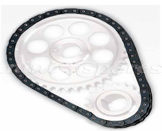
If the increase in the speed for the smaller gear is referred to as a step, our gearbox actually contained two such steps; the speed getting doubled with each step, resulting in a final shaft rotation four times that of the turbine.
Spur gear backlash
It is the amount of tooth space between mating gears at the pitch circle diameter. Backlash may be measured or specified in the transverse, normal, or axial planes, and in the direction of the pit circles or on the line-of-action.
The purpose of backlash is to allow smooth operation and reduce friction by preventing mating gears from grinding by contact on both sides of their gear teeth at the same time.
Minimal or no backlash may cause operation noise, overloading, and overheating of the gears, and even cause seizing and ultimately failure. Large amount of backlash is not desirable, particularly if the gear train must be reverse. Small amount of backlash (clearance) will require tighter tolerances for run-out, pitch, profile, and the location of the operational bearing resulting in an increased cost of gears and assemblies.
Our Project’s Intended Gear System:
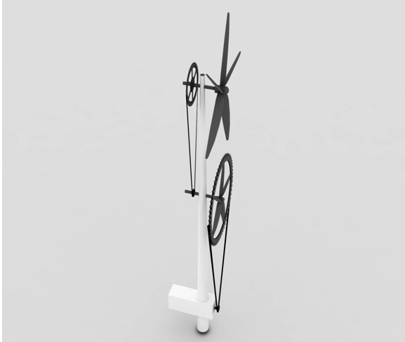
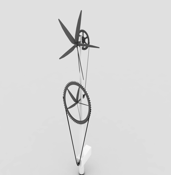
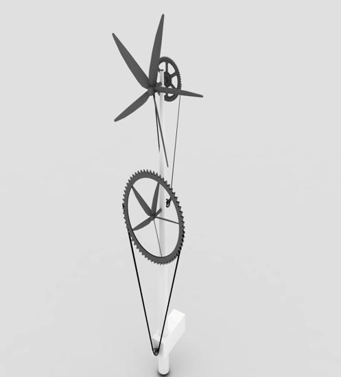
The design in figure 5.5 was the originally intended design. However due to complications, this particular gear system could not be implemented.
This design makes use of a gear and turbine blade hybrid. It’s a basic two step gear transmission system, but the gear/blade hybrid serves the dual purposes of both acting as a gear and as a separate turbine, helping to overcome much of the inertia and friction in the gear system.
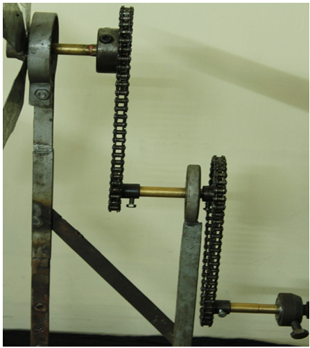
The blade/gear hybrid could not be implemented due to certain complications. The wind generator that was actually assembled used a simple two step gear transformation. The diameters of the smaller gears were half those of the larger ones, resulting in an increase in speed for the generator rotation by a factor of 4.
Electrical Power Generation
Generators:
A generator is an electrical machine that can convert mechanical energy (or power) into electrical energy (or power). The energy conversion is based on the principle of the production of an induced electromotive force (emf).
The adequate generation of electricity is the ultimate goal of our wind system and virtually all power generation systems. The generating unit is usually mounted on the end of the nacelle. Various generating units were considered for the design of our wind turbine, and the suitability of the different units is discussed below.
Vehicle Alternators:
- Advantages: cheap, easy to find, pre-assembled.
- Disadvantages: high rpm required, gears or pulleys needed, low power output, slip rings need maintenance.
- Suitability for Wind Power: Poor
The problem with using car alternators is that they are used to rotate at too high a speed to be used in wind power applications without modifications. Small fast generators working at 600 rpm are still not fast enough for a car or truck alternator. So using a vehicle alternator would require additional use of pulleys and gear systems, which means a lot of power is lost due to friction.
Homemade Permanent Magnet Alternators:
- Advantages: Low cost per watt of output, very efficient, huge power output possible, extremely sturdy construction.
- Disadvantages: A time-consuming, somewhat complicated project, machining needed.
- Suitability for Wind Power: Good
- Homemade permanent magnets have proven to be the most powerful and cost-effective solution for building a wind generator. They can perform efficiently at both low rpm and high rpm. However the complexity in putting together a Permanent Magnet Alternator was too much of an obstacle.
Induction Motor Conversion Alternators:
- Advantages: cheap, easy to find, fairly easy to convert, good low-rpm performance.
- Disadvantages: power output limited by internal resistance, inefficient at higher speeds, machining needed.
- Suitability for Wind Power: Ok
An induction motor can be converted into a low PM alternator at low cost. These tend to produce significant power at low speeds, but become quickly at higher power levels.
DC Generators:
- Advantages: Simple and pre-assembled, some are good at low rpm.
- Disadvantages: High maintenance, most are not good at low rpm, large sizes very hard to find, small ones have limited power output.
- Suitability for Wind Power: Poor to Ok
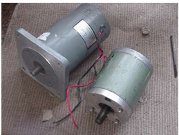
DC generators would be very convenient as one of the goals of our project is to charge DC batteries in a battery bank, and DC output would require no further rectification.
However, they need to rotate at a very high speed to be practical for wind systems. Large DC generators are not really a feasible operation for a small scale wind system, not to mention they are very hard to obtain. Moreover the commutators and brushes require a lot of maintenance.
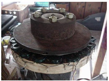
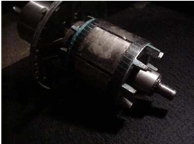
Our Choice for the generating unit – Stepper Motor:
Stepper Motor Basics:
A stepper motor has four coils of wire located 90 degrees away from each other, at positions 12, 3, 6, and 9 o’clock. In the middle is the rotor which spins and has permanent magnets fitted around its circumference. As the rotor spins each magnet in turn approaches, passes and moves away from each of the four coils in turn. A magnet passing a coil of wire causes electricity to flow through that coil and so each of the four coils will have different amounts of electricity flowing through it either one way or the other – alternating current.
Stepper Motor as a Generator:
A stepper motor consists of four coils of wire which are wound separately forming a four- phase motor. This is a major advantage with the stepper motor as it allows a greater production of electricity. If one of the coils has no current flowing through it, it shows that the next coil has reached its maximum. With this operation for 4 phase it will produce more current and voltage. When the four-phases are brought together and rectified (more on rectification later) into direct current (DC), the total electricity generated therefore has a near constant voltage and current.
Figure 6.4: Construction of a Stepper Motor
Reason for choosing stepper motor:
The Stepper Motor was the most viable option for our wind generator. It is perfect for a small scale project. They are one of the most available units, and can be found from old printers, photocopiers, etc. They can generate AC power at low rpm compared to DC generators of similar size. Due to this quality, a wind turbine can be easily attached to a shaft directly rather than onto a shaft that undergoes a very complicated gear mechanism.
Small stepper motors are useful for powering LEDs and after rectification they can charge small batteries very quickly. These batteries can be coupled together to form a larger battery. This reduces the cost considerably.
The biggest advantages are that a small torque and rpm is sufficient to generate a current. As compared to other generating units, this requires the least rpm and the least torque for generation of electricity.
Basics of an Inverter
Inverter:
An inverter is an electrical device that converts direct current (DC) to alternating current (AC). The inverter can meet any voltage and frequency requirements with the right switching and control circuits.
Inverters are mostly used to supply AC power from DC sources such as batteries, solar panels, wind generators or other renewable energy sources.
The inverter has the opposite function of a rectifier, which converts AC to DC power.
Reason for using inverter:
Wind generators depend on steady wind flow to provide power. We can eliminate the dependence on a constant wind flow by using a wind generator inverter.
A small wind turbine under 5 kilowatts uses a battery bank to store the extra energy that is created with a wind turbine. A series of batteries are charged which can later supply DC power. But most household appliances require AC power to operate.
A wind generator inverter converts the DC power from the battery bank into AC power to be distributed to the house or residence it is connected to.
Basic Design of an Inverter:
Top: Simple inverter circuit shown with
an electromechanical switch.
Bottom: Automatic equivalent auto-switching
device implemented with two transistors and
split winding auto-transformer in place of the
mechanical switch.
Source: Wikipedia
Here we have a basic circuit of an inverter. DC power is supplied through the centre tap of the primary winding of the transformer. A switch is used to switch between the two different paths that current can flow, thereby generating alternate voltage in the secondary winding.
In earlier versions of the inverter, an electromechanical switch was used. The electromechanical switch includes two stationary contacts and a spring supported movable contact. The spring holds the movable contact against one of the stationary contacts and an electromagnet pulls the movable contact to the opposite stationary contact. The current in the electromagnet is interrupted by the action of the switch so that the switch continually switches rapidly back and forth.
Eventually, transistors and other semiconductor devices were used for the switching action. The use of transistors as the switching device will be covered in the following section, where we discuss the modern inverter in detail.
Modern Inverters:
Modern inverters use a basic circuit scheme like that shown in the following figure.
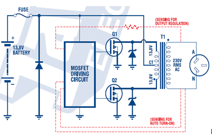
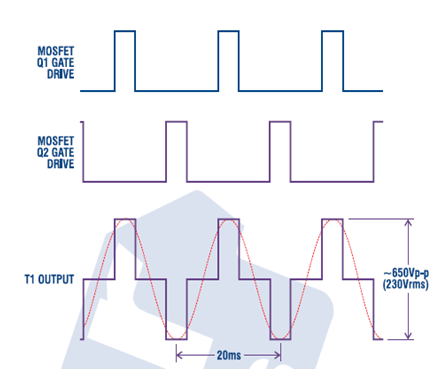
The DC from the battery is converted into AC very simply, by using a pair of power MOSFETs (Q1 and Q2) acting as very efficient electronic switches. The positive 13.8V DC from the battery is connected to the centre-tap of the transformer primary, while each MOSFET is connected between one end of the primary and earth (battery negative). So by switching on Q1, the battery current can be made to flow through the ‘top’ half of the primary and to earth via Q1. Conversely by switching on Q2 instead, the current is made to flow the opposite way through the ‘lower’ half of the primary and to earth.
Therefore by switching the two MOSFETs on alternately, the current is made to flow first in one half of the primary and then in the other, producing an alternating magnetic flux in the transformer’s core. As a result, a corresponding AC voltage is induced in the transformer’s secondary winding, and as the secondary has about 24 times the number of turns in the primary, the induced AC voltage is much higher: around 650V peak to peak.
The inverter does not produce a pure sine wave like the AC mains power supply, because the switching MOSFETs are simply turned on and off. The output voltage is actually alternating rectangular pulses.
However the width of the pulses and the spacing between them is chosen such that the ratio between the RMS value and its peak-to-peak value is quite similar to that of a sine wave. The resulting waveform is called a ‘modified sine wave’ and as the RMS voltage is close to 230V many AC appliances are able to operate from such a waveform without problems.
But this time of waveform is not close enough to a sine wave for some appliances, because the rectangular pulses contain not just the fundamental mains frequency but quite a lot of its harmonics as well. These harmonics can destroy the operation of some appliances.
Important Features of an Inverter:
Voltage Regulation:
Inverters obviously cannot provide output regulation like the mains power supply, which is very well regulated. The electricity supplier has enormous generating plants with automatic regulation systems to keep the mains voltage and frequency close to constant, despite load variations of many megawatts.
They can however provide a reasonably good regulation for loads up to their rated capacity.
In this type of inverter, it isn’t feasible to control the peak-to-peak output, because this is largely fixed by the battery voltage and the transformers step-up ratio.
So in most cases the regulation is achieved in a different way: by varying the width of the rectangular pulses, to control the ‘form factor’ and hence the RMS value of the output voltage.
This is called pulse width modulation (PWM), and is usually done by having a feedback system which senses the inverter’s output voltage (or load current). When this feedback senses that the load on the inverter’s output has increased, the inverter’s control circuitry acts to increase the width of the pulses which turn on the MOSFETs.
So the MOSFETs turn on for longer each half-cycle, automatically correcting the RMS value of the output to compensate for any drop in peak-to-peak output. However, this approach does have its limitations, because it only increases the pulse-width up to a certain point. This may not allow the inverter to deliver enough power in ‘surge’ conditions.
When most appliances turn on, they draw a ‘starting’ current which is many times greater than the current drawn when the appliance is running. This type of surge can overload the inverter, prompting its protection circuitry to shut down to prevent damage to transformer and MOSFETs.
Some inverters employ a ‘soft-start’ circuitry to allow the inverter to cope with load current surge. The output voltage and power drops, but at least the inverter continues operating and allows the appliance to turn on.
There are some devices with an extremely high starting current, where an inverter simply cannot be used. Examples include freezers, air conditioners, etc. This type of appliance should be powered with an engine driven alternator rather than an inverter.
Voltage Spikes/ Surge Capacity:
Appliances with fairly inductive load impedance can develop high voltage spikes due to ‘back EMF’. These voltage spikes can be transferred back to the primary of the transformer where they could very well damage the MOSFETs and their driving circuitry. The risk of damage is small during one of the power pulses, because one of the primaries is earthed. It is greatest when neither of the MOSFETs conduct leading to excessive voltage across the MOSFETs.
As a preventive measure, many inverters have a pair of Zener diodes across the MOSFETs. The Zener diodes conduct whenever the voltage across the MOSFETs increases excessively, thus protecting them.
Auto Starting :
Some inverters are provided with an ‘automatic turn on/off’ feature. They stop working when an AC load is removed but turn on again when it is connected. This ‘auto turn-on/off’ feature is also known as ‘load demand’, ‘sleep mode’ and other names.
Simply turning on the AC appliance, switches the inverter into ‘on’ mode and it starts supplying AC power. This is very beneficial as it allows us to conserve battery energy, while allowing the appliance to operate in exactly the same way as it is connected to mains supply.
In most cases this auto turn-on system uses a sensing circuit connected into the Inverter’s output loop, and designed to detect when the appliance switch is closed to complete the high voltage circuit. This allows a small DC sensing current to flow, and this current is used to turn on the inverter’s MOSFET drive circuitry.
When no DC flows in the output loop, the drive circuitry is disabled and no pulses are fed to the gates of the MOSFETs. As a result, they don’t conduct, and the inverter doesn’t operate. Only a very small standby current is drawn from the battery.
True Sine wave Inverters :
Most inverters deliver a ‘modified sine wave’ output voltage because they use MOSFET transistors as electronic switches. Although the conversion efficiency is very high, the output waveform of alternating pulses is very rich in harmonics.
Appliances such light dimmers, variable speed drills and laser printers will not run satisfactorily with such a ‘modified sine wave’. So some manufacturers build a few models that deliver a pure sine wave output. This results in more complex circuitry for the inverters, because it is not easy producing a pure sine wave output while converting DC to AC efficiently. Consequently, pure sine wave inverters are usually more expensive for the same power rating.
The most common type of pure sine wave inverter operates by first converting the low voltage DC into high voltage DC, using a high frequency DC-DC converter. It then uses a high frequency PWM system to convert the high voltage DC into chopped AC, which is passed through an L-C low pass filter to produce the final clean 50Hz sine wave output. This is like a high-voltage version of the single-bit digital to analog conversion process used in many CD players.
Off-grid systems and Grid-tie systems:
Off grid systems are standalone wind generating systems that are only connected to supply a particular residence of choice. They are not connected to the main utility line, hence the name ‘off-grid’ wind system.
A small off-grid wind system consists of a wind turbine, a controller, a battery bank that stores the power, an inverter and a tower. Standalone wind energy systems might be used at remote locations such as a cabin, cottage, for agricultural use or a monitoring station.
The inverter for an off-grid system is called a standalone inverter, which is basically the inverter model that has been discussed so far.
Grid-tie systems are connected to the grid. Depending on the amount of power being used by the household, electricity is either fed to or accepted from the utility.
When wind flow is not sufficient, the grid-tie system can draw electricity from the grid – exactly the way mains power is normally drawn. When it is producing power in excess of the household requirement, it can be fed into the main power grid. The inverter used is called a synchronous inverter, which can be used for net metering depending on the location and mains power supplier.
Many local power grids in the United States apply a form of credit system, where power fed into the main grid by a self generating unit, can be stored as credit which pays for a portion of future usage of mains power.
The inverter monitors the alternating current waveform from the Mains supply, and generates AC output that is phase matched with the mains.
Choosing the right inverter:
The inverter is one of the most important and most complex components in an independent energy system. To choose an inverter, one should know some basic functions, capabilities, and limitations.
Define the need:
To choose an inverter, one should first define his/her needs. Inverter manufacturers print everything one needs to know on their specification sheets. Here is a list of the factors that one should consider.
Operating Environment:
Where is the inverter to be used? Inverters are available for use in buildings, for recreational vehicles, boats, and portable applications. Will it be connected to the utility grid in some way? Electrical conventions and safety standards differ for various applications, so it’s important to check.
Electrical Standards:
The DC input voltage must conform to that of the electrical system and battery bank. 12 volts is no longer the dominant standard for home energy systems, 24 and 48 volts are the common standards now. A higher voltage system carries less current, which makes system wiring cheaper and easier.
The inverter’s AC output must conform to the conventional power in the region in order to run locally available appliances. The standard for AC mains service in the UK is 230 volts at a frequency of 50 Hertz (cycles per second).
Power Capacity:
How much load can an inverter handle? Its power output is rated in watts (watts = amps x volts). There are three levels of power rating – a continuous rating, a limited-time rating, and a surge rating. Continuous means the amount of power the inverter can handle for an indefinite period of hours. When an inverter is rated at a certain number of watts, it generally refers to its continuous rating.
The limited-time rating is a higher number of watts that it can handle for a defined period of time, typically 10 or 20 minutes. The inverter specifications should define these ratings in relation to ambient temperature (the temperature of the surrounding atmosphere). When the inverter gets too hot, it will shut off. This will happen more quickly in a hot atmosphere. The third level of power rating, surge capacity, is critical to its ability to start motors, and is discussed below.
Some inverters are designed to be interconnected or expanded in a modular fashion, in order to increase their capacity. The most common scheme is to “stack” two inverters. A cable connects the two inverters to synchronize them so they perform as one unit.
Power Quality – SINE Wave vs. Modified SINE Wave:
Some inverters produce “cleaner” power than others. Simply stated, “sine wave” is clean; anything else is dirty. A sine wave has a naturally smooth geometry, like the track of a swinging pendulum. It is the ideal form of AC power. The utility grid produces sine wave power in its generators and normally delivers it to the customer relatively free of distortion. A sine wave inverter can deliver cleaner, more stable power than most grid connections.
How clean is a “sine wave”? The manufacturer may use the terms “pure” or “true” to imply a low degree of distortion. The facts are included in the inverter’s specifications. If the total harmonic distortion (THD) is lower than 6 percent it should satisfy normal home requirements. Look for less than 3 percent if you have unusually critical or sensitive electronics, as in a recording studio.
Other specs are important too. RMS voltage regulation keeps your lights steady. It should be plus or minus 5 percent or less. Peak voltage (Vp) regulation needs to be plus or minus 10 percent or less.
A “modified sine wave” inverter is less expensive, but it produces a distorted square waveform that resembles the track of a pendulum being slammed back and forth by hammers. In truth, it isn’t a sine wave at all. The misleading term “modified sine wave” was invented by advertising people. Engineers prefer to call it “modified square wave.”
The “modified sine wave” has detrimental effects on many electrical loads. It reduces the energy efficiency of motors and transformers by 10 to 20 percent. The wasted energy causes abnormal heat which reduces the reliability and longevity of motors and transformers and other devices, including some appliances and computers. The choppy waveform confuses some digital timing devices.
About 5 percent of household appliances simply won’t work on modified sine wave power at all. A buzz will be heard from the speakers of nearly every audio device. An annoying buzz will also be emitted by some fluorescent lights, ceiling fans, and transformers. Some microwave ovens buzz or produce less heat. TVs and computers often show rolling lines on the screen. Surge protectors may overheat and should not be used.
Modified sine wave inverters were tolerated in the 1980s, but since then, true sine wave inverters have become more efficient and more affordable. Some people compromise by using a modified wave inverter to run their larger power tools or other occasional heavy loads, and a small sine wave inverter to run their smaller, more frequent, and more sensitive loads. Modified wave inverters in renewable energy systems have started fading into history.
Efficiency :
It is not possible to convert power without losing some of it. Power is lost in the form of heat. Efficiency is the ratio of power out to power in, expressed as a percentage. If the efficiency is 90 percent, 10 percent of the power is lost in the inverter. The efficiency of an inverter varies with the load. Typically, it will be highest at about two thirds of the inverter’s capacity. This is called its “peak efficiency.” The inverter requires some power just to run itself, so the efficiency of a large inverter will be low when running very small loads.
In a typical home, there are many hours of the day when the electrical load is very low. Under these conditions, an inverter’s efficiency may be around 50 percent or less. The full story is told by a graph of efficiency vs. load, as published by the inverter manufacturer. This is called the “efficiency curve.” These curves should be read carefully. Some manufacturers cheat by starting the curve at 100 watts or so, not at zero.
Because the efficiency varies with load, one should not assume that an inverter with 93 percent peak efficiency is better than one with 85 percent peak efficiency. If the 85 percent efficient unit is more efficient at low power levels, it may waste less energy through the course of a typical day.
Internal Protection:
An inverter’s sensitive components must be well protected against surges from nearby lightning and static, and from surges that bounce back from motors under overload conditions. It must also be protected from overloads. Overloads can be caused by a faulty appliance, a wiring fault, or simply too much load running at one time.
An inverter must include several sensing circuits to shut itself off if it cannot properly serve the load. It also needs to shut off if the DC supply voltage is too low, due to a low battery state-of-charge or other weakness in the supply circuit. This protects the batteries from over-discharge damage, as well as protecting the inverter and the loads. These protective measures are all standard on inverters that are certified for use in buildings.
Inductive loads and Surge Capacity:
Some loads absorb the AC wave’s energy with a time delay. These are called inductive loads. Motors are the most severely inductive loads. They are found in well pumps, washing machines, refrigerators, power tools, etc. TVs and microwave ovens are also inductive loads. Like motors, they draw a surge of power when they start.
If an inverter cannot efficiently feed an inductive load, it may simply shut down instead of starting the device. If the inverter’s surge capacity is marginal, its output voltage will dip during the surge. This can cause a dimming of the lights in the house, and will sometimes crash a computer.
Any weakness in the battery and cabling to the inverter will further limit its ability to start a motor. A battery bank that is undersized, in poor condition, or has corroded connections, can be a weak link in the power chain. The inverter cables and the battery interconnect cables must be big, perhaps the size of a large thumb! The spike of DC current through these cables is many hundreds of amps at the instant of motor starting. Coat battery connections have a protective coating to reduce corrosion.
Idle Power:
Idle power is the consumption of the inverter when it is on, but no loads are running. It is “wasted” power, so if one expects the inverter to be on for many hours during which there is very little load (as in most residential situations); he would want this to be as low as possible. Typical idle power ranges from 15 watts to 50 watts for a home-size inverter. An inverter’s spec sheet may describe the inverter’s “idle current” in amps. To get watts, just multiply the amps times the DC voltage of the system.
Low switching frequency vs. High switching frequency:
There are two ways to build an inverter. Without diving into theory, there are differences in weight, cost, surge capacity, idle power, and noise.
A low switching frequency inverter is big and heavy (generally 10 kg per kilowatt and more expensive. It has the high surge capacity (four to eight times the continuous capacity) needed to start large motors. The acoustical buzz that low switching frequency inverters make can be a big problem.
A high switching frequency inverter is much smaller and lighter (generally about 2.5 kg per kilowatt and also less expensive. It has less surge capacity, typically about two times the continuous capacity. It produces little or no audible noise. The idle power is generally higher. If the inverter is oversized for motor starting, its idle power will be higher yet, and may be prohibitive. Most homes that have a well pump or other motors greater than 1 HP will find a low switching frequency inverter to be more economical.
Both types of inverters have their virtues. Some people “divide and conquer” by splitting their loads and using two inverters. This adds a measure of redundancy. If one ever fails, the other one can serve as backup.
Automatic ON/OFF:
Inverter idling can be a substantial load on a small power system. Most inverters made for home power systems have automatic load-sensing. The inverter puts out a brief pulse of power about every second (more or less). When you switch on an AC load, it senses the current draw and turns itself on. Manufacturers have various names for this feature, including “load demand,” “sleep mode,” “power saver,” “auto-start,” and “standby.”
Automatic on/off can make life awkward because a tiny load may not trigger the inverter to turn on or stay on. For example, a washing machine may pause between cycles, with only the timer running. The timer draws less than 10 watts. The inverter’s turn-on “threshold” may be 10 or 15 watts. The inverter shuts off and doesn’t come back on until it sees an additional load from some other appliance. You may have to leave a light on while running the washer.
Some people can’t adapt to such situations. Therefore, inverters with automatic on/off also have an always-on setting. With it, low-power night lights, clocks, fax, answering machines and other tiny loads can be run, without losing continuity. In that case, a good system designer will add the inverter’s idle power into the load calculation (24 hours a day). The cost of the power system will be higher, but it will meet the expectations of modern living.
The Inverter in our project:
Fig 7.7: Schematic of our Inverter
The MOSFETs perform the switching function, to allow current to flow first through one direction, and then through another, to create alternating voltage on the primary side of the transformer. The switching of the MOSFETs is maintained by the gate pulses that it receives from the timing circuit, in this case the IC- CD4047BE.
CD4047BE is primarily a CMOS Low-Power Monostable/Astable Multivibrator. The key reason MOSFETS were used is because they are the most efficient current switches.
An added feature in our inverter was a RC tuning circuit to adjust the frequency of the output voltage according to requirement.
Figure 7.8: Pin configuration of CD4047BE
Inverter Components:
Resistor:
A resistor is a two-terminal electronic device. It obeys Ohm’s law at room temperature; the voltage produced across its terminals is proportional to the electric current through it.
V = IR
Resistors are elements of electrical networks and electronic circuits and are present in almost all day to day appliances. Practical resistors can be made of various compounds and films, as well as resistance wire (wire made of a high resistivity alloy, such as nickel-chrome).
Capacitor:
A capacitor is a two terminal device mainly used to store charge. It is a passive electronic device just like a resistor but one of the main differences is that it consists of two metal plates that are separated by a medium known as a dielectric. A capacitor begins to charge when there is a potential difference across it; an electric field is developed across the capacitor.
Capacitors are given fixed values to indicate how much charge they can store, which is called the capacitance. Capacitance of a capacitor is measured in farads. This is the ratio of the electric charge on each conductor to the potential difference between them.
Capacitors are used in our daily life for example they are used to block dc current, filter networks, for smoothing the output of power supplies that where block shaped, zigzagged etc.
They are also used as tuning circuits etc.
Potentiometers:
A potentiometer is an electronic device that can be used to vary or adjust the voltage developed across it. The potentiometer is a three terminal device. It consists of a knob which can be easily rotated to change the resistance of the potentiometer, and hence vary the voltage.
A common example is a volume control for a radio receiver.
Diodes:
A diode is a two-terminal electronic component that conducts electric current in only one direction. The term usually refers to a semiconductor diode, the most common type today. This is a crystalline piece of semiconductor material connected to two electrical terminals.
The main purpose of a diode is to allow an electric current to pass in one direction (called the diode’s forward bias direction) while opposing current in the opposite direction (the reverse direction) such that the current becomes zero for a negative current or current in moving in the opposite direction. Thus, the diode can be thought of as an electronic version of a check valve. This behavior that allows current to flow in one direction is known as rectification, and is used to convert alternating current to direct current, and to extract modulation from radio signals in radio receivers.
Diode (V-I) characteristics:
A power diode is a PN junction device that is used to restrict the flow of current or it opposes the change in electricity. When the potential across the anode is greater (positive) compared to the cathode, the diode is said to be in the forward bias and the diode conducts. When the potential across the cathode is greater (positive) compared to the anode, the diode is said to be in the reverse bias and the diode does not conduct. It acts like an open circuit; no conduction takes place. In this condition, a small amount of current flows through the diode. This current is known as leakage current and this is in the range of micro-milli amperes. The leakage current slowly builds and this causes the reverse voltage to reach the Zener region or the Avalanche voltage. This voltage can result in the diode from collapsing and acting as a short wire.
The V-I characteristic curve can be broken down into three parts:
- Forward –biased region, where Vd > 0
- Reverse-biased region, where Vd <0
- Breakdown region, where Vd <-VBR
Forward –biased region:
In this region, the diode is in a conduction state, Vd> 0. The diode current passing through the diode is very small if the voltage across the diode is less than 0.7V i.e. threshold voltage. When voltage across the diode is above the threshold voltage, the diode conducts fully.
Reverse-biased :
In the reverse biased region, Vd < 0. When the voltage across the diode is negative, the current flow is very small and this small current is known as the leakage current.
Breakdown region
In the breakdown region, the reverse voltage is such that it causes the leakage current to increase. The leakage current in turn starts to increase very rapidly. This causes the diode to work in the breakdown region. The operation of the diode in the breakdown will not damage the diode, but due to safety reasons it is advisable that a very high voltage should not be applied.
MOSFET:
MOSFETs are metal oxide field effect transistors. The metal oxide helps in the dissipation of heat and prevents a FET from over- heating. This solves the problem of overheating but MOSFETs are still very difficult to protect from short circuited fault conditions.
The advantage of using MOSFETs is that they are very fast for switching. MOSFETs have the problem of electrostatic discharge and hence they have to be handled with care. For an inverter circuit an enhancement type MOSFET is preferred compared to a depletion type. The main reason behind this selection is that a depletion type MOSFET’s gate is still on when the voltage at the gate is zero. An enhancement type MOSFET is used because it acts more like a switch.
When a positive voltage is applied with respect to the source, the MOSFET’s electric field pulls electrons from the n+ layer to the p+ layer. This opens a channel closet to the gate, which as a result causes a current to flow from drain to source.
MOSFETs require very low gate energy to be switched on, and they have a very high switching speed and low switching loss. However MOSFETs suffer from the disadvantage of high forward on-state resistance. As a result there is a high loss during on-state operation.
Steady-state characteristics:
There are three regions in which a MOSFET operates
- When Vgs < Vt , cut-off region
- When Vds > Vgs – Vt , saturation region
- When Vds = Vgs – Vt, linear region
Figure 8.5: Drain Characteristic Curve of MOSFET
Cut –off Region:
In this region, the MOSFET does not work. It remains inactive similar to an open circuit. The electrostatic field does not have the capability to pull the electrons. Hence there will be no current flow from drain to source.
Linear Region:
In this region the increase in current is directly proportional to increase in voltage, so it obeys Ohm’s Law. Here the MOSFET acts like an amplifier.
Saturation Region:
In this region, the drain current tends to saturate as the voltage across the drain increases. In this case, the MOSFET tends to act like a switch.
Rectifier:
A rectifier is an electrical circuit that is used to convert alternating current (AC) into direct current (DC). This process is known as rectification. Rectifiers may be made of solid state diodes, vacuum tube diodes, mercury arc valves, and other components. Rectifiers have many uses including being used as components of power supplies and as detectors of radio signals.
Half-wave rectification:
In a half-wave rectifier, only half the portion is allowed to pass whether it be a positive or a negative. In this case, only the positive portions are allowed to pass.
Since only half the input is obtained for the output, this is called half-wave rectification. The result of obtaining only half the portion for one complete cycle makes it inefficient for power transfer. Half-wave rectification can be achieved with a single diode in a single phase supply, or with three diodes in a three-phase supply.
Full-wave rectification:
A full-wave rectifier converts the whole of the input waveform to one of constant polarity (positive or negative) at its output. Full-wave rectification converts both polarities of the input waveform to DC (direct current), and is more efficient. However, in a circuit with a non-center tapped transformer, four diodes are required instead of the one needed for half-wave rectification. Four diodes arranged this way are called a diode bridge or bridge rectifier:
Transformer:
A transformer is a circuit that transfers energy from one circuit (primary) to another circuit (secondary) through inductively coupled electrical conductors.
A changing current in the primary circuit creates a changing magnetic field. This changing magnetic flux produces a changing magnetic flux in the secondary circuit, which induces an alternate voltage in the secondary coil.
Here are some basic characteristics of a transformer:
- The transformer transfers electric power from one circuit to another.
- It does this without a change in frequency.
- It does this by electromagnetic induction.
- Here the two electric circuits are in mutual inductive influence of each other.
Transformers can have two types of functions:
1. Step up
2. Step down.
Step up transformers boost the voltage to a higher value than in the primary. Step down transformers lower the voltage.
The ratio of the secondary to primary Voltage (Vs/Vp) is given by turn ratio of the coils on each side.
Figure 8.8: A Transformer Core showing the primary and secondary windings
Feasibility & Cost Benefit Analysis
Feasibility:
The feasibility of generating electricity from wind energy depends on a couple of crucial factors. These factors will be explained shortly. It is very important to mention that with time, different methods have been considered for the implementation of wind powered turbine. However, before they can be implemented, many criteria have to be full-filled of the criteria will now be discussed.
Site Selection:
Site Selection plays a very crucial part in the implementation of wind generators. Wind generators need to be installed in places where the availability of wind needs to be constant and the direction of wind flow must be constant or should have a low variance. Places where wind flow is available, but the direction of the wind changes continuously creates a problem. Such places have multiple sensors, in-order to make sure that the wind turbines face the correct position in order to have a complete and efficient rotation. This may seem very useful but these implementations tend to take a large area, which is very expensive, requires a lot of maintenance and the sensors need to have a high order of precision.
The ground surface:
The rougher the ground surface the more it interferes with the wind. Rough ground creates turbulence in the layers of wind above it. Here roughness means obstacles like woodlands, buildings etc.
Hills, valleys and ridges:
Rounded hills, crests and ridges generally experience higher but more variable wind speeds than flat ground. The wind is accelerated over the hills. However, on the downwind side of the hill there may be turbulence. The amount that the wind accelerates over a hill or ridge depends strongly on the height and shape of the hill. It is important to mention that higher ground usually experiences stronger winds than lower ground.
Coastal areas:
Coastal areas (around large lakes as well as near the sea) are likely to have stronger winds than inland areas. The increase in wind due to a costal location is not easily quantifiable. Sea breezes usually have a diurnal pattern due to the temperature difference between the sea and land. They generally blow from the land to the sea during day and from the sea to the land at night.
Choosing the wind turbine site:
The wind turbine should be sited to receive the maximum amount of wind in terms of both wind flow duration and wind speed. In practice, this means choosing a site which:
- Is far from obstructions (tall trees, high buildings).
- Is high up.
- Receives the prevailing wind.
- Avoids turbulent air streams.
Seasonal Changes:
It is important to know that wind patterns do not remain the same throughout the year. These changes have a very small effect in some places and a considerable affect in other places. Countries that have continuous amount of wind flow that is sufficient for generation of electricity tend to be less affected by this small change e.g. Norway, Denmark etc. However in countries where the wind flow is less, and there is a lot of fluctuation, for example Bangladesh, the feasibility of implementing large scale wind turbine generators in such places is slim.
Financial:
This plays the most important role after the site selection. After a feasibility analysis is conducted, most governments or private organizations weigh the financial costs for such an investment. Most third world countries tend to avoid the prospect of installing a wind turbine generator because of the large funds necessary. Countries without financial restraints are a lot bolder with such investments. For developing countries it is still not practical enough to construct large scale wind farms, without investment from multinational companies.
Cost benefit analysis:
Mechanical Parts:
| Parts | Price | Units | Cost (Taka) |
| Large bearings | 650 | 2 | 1300 |
| Small bearings | 550 | 2 | 1100 |
| Small gears | 250 | 2 | 500 |
| Larger gears | 450 | 2 | 900 |
| Chain | 450 | 2 | 900 |
| Shaft | 550 | 1 | 550 |
| Blade | 450 | 1 | 450 |
| Miscellaneous | 2000 | ||
| Total | 7700 | ||
Electrical Parts:
| Parts | Price | Units | Cost (Taka) |
| LED (1.5V) | 60 | 4 | 240 |
| Circuit board | 35 | 2 | 70 |
| Capacitor | 40 | 1 | 40 |
| Resistor | 5 | 4 | 20 |
| Pot | 50 | 1 | 50 |
| Diode | 15 | 3 | 45 |
| Battery (1.5V) | 30 | 2 | 60 |
| MOSFET | 70 | 2 | 140 |
| CMOS multivibrator | 120 | 1 | 120 |
| Transformer | 1200 | 1 | 1200 |
| Total 1985 | |||
Grand total = Tk. 9685
Current wind systems in Bangladesh:
The prospect of generating electricity from wind flow has improved over the years. Bangladesh’s first-ever generation of electricity from wind at a 900-kilowatt plant has ushered in new hopes for generation of power with minimum cost in the country. Chief Engineer of PDB and Director of some wind projects, Khizir Khan was quoted as saying that it takes only 1.18 taka (about 2 US cents) to generate each kilowatt power from wind while average kilowatt generation cost in other power plants is 3 taka (5 US cents).
Bangladesh Power Development Board (BPDB) implemented the project under a pilot program. The main specialty of this unique wind energy system is to generate electricity at 440V and the longevity of this sort of plant is almost 20 to 30 years.
“Wind energy is technically feasible, financially viable and environment-friendly,” Khan said. “We will put forward recommendations to the government about economic viability of the plant and request the authorities concerned to set up more wind- power plants.”
There are currently many projects underway. Some of the more prominent ones will be discussed below.
Wind Energy Program by Bangladesh Power Development Board (BPDB):
BPDB (Bangladesh Power Development Board) is implementing a pilot project of 0.90 MW capacity of the Grid Connected Wind Energy (GCWE) in the Muhuri Dam areas. The installation, commissioning and erection work of 4 units of the 225 kW GCWE turbines is at this moment progressing very fast. After the successful implementation of the pilot project of 0.90 MW, with 1 MW unit capacity wind turbines, this site is suitable for at least 100 MW wind electricity. It was established at a cost of 90 million taka (1.5 million US dollars) including 19.3 million taka (320,000 US dollars) for feasibility study. It is now ready to generate electricity from wind and supply to the Muhuri Irrigation Project and the national grid, according to The Bangladesh Observer.
Wind energy installation under renewable Energy Program (REP) under BPDB:
- Energy Resource : Wind Turbine
- Type of installation : Water pumping wind mill Irrigation
- No of installation : 1
- Capacity of installation : 1 x 1.0 Kw, 3 x 1.5 Kw, 1 x 10 Kw
- Location of Installation : Patenga (Coastal Area), Chittagong)
- Functional Status : Functioning
- Energy Resource : Wind
- Type of installation : Resource Assessment
Moreover 1 MW New Wind Project at Kutubdia currently on going.
Total installation by BPDB = 2 MW
Demonstration of Wind Energy Technology under Local Government Engineering Department (LGED):
Wind energy utilization in Bangladesh is in the early stage of application. Several locations have already been assessed to evaluate the wind energy potential of the coastal region of the country. Variation of wind resource has been observed among the different locations in the region. In addition, seasonal variation of wind resource prevails in the country, with a strong potential during the months of April to September, and a very weak potential during rest of the year. However, scope of utilization of wind energy resources can become effective in certain cases of exclusive applications including wind water pumping and power generation through Wind-Diesel-hybrid systems. So far LGED has installed largest Wind-Solar Hybrid System which is 10Kwp in Saint Martins Island at Bay of Bengal. One small unit also installed at tourist resort Kuakata sea beach.
Wind-Solar Hybrid System in Kuakata Sea Beach:
In the coastal belt of Bangladesh, the average wind speed is high and is sufficient to generate electricity. Conventional energy resources are being depleted and biomass faces a growing risk of depletion in many parts of the world. Besides, use of fossil fuels creates serious environmental problem. Emission of greenhouse gases through burning fossil fuels is linked with global warming, sea-level-rise and degradation of environment quality. Limited production of conventional energy and high transmission and distribution cost would not permit the expansion of electricity network for the people living in the remote and coastal areas in the foreseeable future. Wind energy can be considered to be especially suitable for such inaccessible costal areas which can meet the electricity demands of those deprived people. Currently, appropriate lack of wind speed limits large-scale programs for harvesting wind energy on commercial basis. However small wind turbines hold potential for demonstrating the technology as well as raising awareness of the people about the prospect and benefit of using wind energy in Bangladesh.
- Location: LGED Guest house cum cyclone shelter, Kuakata Sea-beach, Kalapara, Patuakhali.
- Capacity: 400 Watt
- Wind Turbine: 400 watt, Air 403 Model (Marine Version)
- Rotor Diameter: 46 Inches(1.17 meters)
- Start up wind speed: 7mph(3.0 m/s)
- Impact: Demonstration of Technology, enhanced tourism in Kuakata
Wind Energy Program under Grameen Shakti:
Wind Energy Program: Grameen Shakti is experimenting with the possibility of developing systems to utilize wind energy in the coastal areas of Bangladesh. GS installed 4 hybrid power stations (combination of wind turbine and diesel generator) in four cyclone shelters of Grameen Bank.
| turbines is connected |
Off which 3 are 1.5 kW and one is 10 kW. Power generated from the wind to four cyclone shelters for lighting. Three of which are for Grameen Bank and one exclusively used as cyclone shelter. Appliances used with these systems are lights, fans, televisions, water pumps, incubators.
Hybrid System of Grameen Shakti:
Energy Resource: Wind-Diesel Hybrid System
- Type of installation: Hybrid
- No of installation: 7
- Capacity of installation: 4.32 KW
- Cost of Installation: 4.5 lacs
- Location of Installation: Coastal Area of Bangladesh
- Functional Status: Functioning
- Type of installation: Resource Assessment
Wind Energy Program under Bangladesh Center for Advanced Studies (BCAS)
Wind energy installation under Renewable Energy Program (REP):
- Energy Resource : Wind Turbine
- Type of installation : Water pumping wind mill Irrigation
- No of installation : 1
- Capacity of installation : 1×1.0 Kw, 3×1.5 Kw, 1×10 Kw
- Location of Installation: Patenga (Coastal Area), Chittagong)
- Functional Status : Functioning
- Energy Resource : Wind
- Type of installation : Resource Assessment
Wind Energy Program under Bangladesh Rural Advancement Committee (BRAC):
Wind energy installation under Renewable Energy Program (REP):
- Energy Resource: Wind Turbine
- Type of installation: Stand-alone
- No of installation: 10
- Capacity of installation: 0.3 KW
- Location of Installation: Coastal Area of Bangladesh
- Functional Status : Functioning
- Energy Resource: Wind
- Type of installation: Resource Assessment
Wind Power Density by territory:
Figure 9.1: Wind Power Density Map of Bangladesh
Average Speed and Wind Power Density by location
Discussions and Conclusion
Here in this chapter we have discussed briefly what our exact plan was and how much we can achieve during accomplishing the work and because off some problems what are the changes we have to make in our plan.
Discussions:
In this project we have tried to implement a wind turbine such that by using natural resources like wind energy we could generate electricity. The design we came up with is different from the standard design and we found that considering the fact of low wind flow, our design would generate sufficient power. We thought that since electricity is generated via the rotation of the blade turbine, by increasing the number of rotations we could generate a lot more power. As a result we came up a two-step gear system, where the main turbine blade would rotate by a factor of 4.
The electricity generated then would be stored in a battery which would be used to power devices. Since most electrical and electronic devices operate in AC, the use of an inverter is crucial so part of our project is also to convert the DC voltage generated via wind energy to AC power. In the inverter, we have added a tuning circuit which would help regulate the frequency of the AC voltage that is being delivered.
Our Wind Generator:
Our Wind Generator comprises of
- A stepper motor as the generating unit.
- Turbine blades made of low quality steel.
- A battery bank.
- Two sets of LEDs
(one set to indicate batteries are being charged, and the other turning on when they are fully charged).
- Two step Gear System (increased generator rotation speed by a factor of 4).
- Inverter
Drawbacks of our system:
One of the main drawbacks of our generator was the poor quality of our turbine blades. Due to financial and time constraints, the originally intended gear system could not be built. Furthermore, the gear system that was eventually built turned out to be too heavily loaded. The excessive inertia due to the loading made it very difficult to get proper rotation of the turbine.
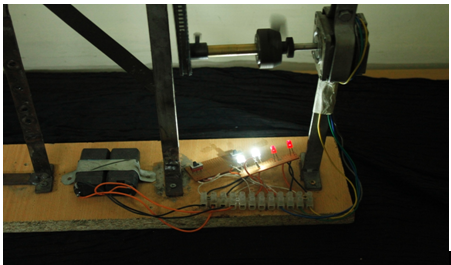
Further prospects:
Unfortunately, generating electricity from wind power tends to be a poor prospect in Bangladesh due to a lot of constraints, one of which is financial. However, the biggest problem faced is the lack of wind flow in Bangladesh and the lack of research that has been done. Even with these problems, it is worth mentioning that there have been foreign investors who were interested in installing wind turbine generators, but due to the lack of concrete data most of these projects failed.
It was known from the start of the project that the feasibility was very poor and that was taken into account. It was mentioned that a wind power station would not generate adequate power to supply to the national power grid. Taking that fact into account, the goal quickly shifted to stand-alone systems. Stand alone systems are independent systems used to power a home or a small firm. They are not connected to the national grid.
This project was specifically designed for stand-alone systems in areas where adequate wind flow is readily available. The prospect of wind flow in Dhaka city was found to be futile. This project was for rural areas that experience power failure and where national grid power is not an option, for example, hilly areas, small isolated islands, forests. One of the main motivations for this experiment was that it was cheap and easy to install and did not require much maintenance. Also the parts for this project were easily available.
The biggest advantage is that the same gear system can be applied for hydro electric turbines. These can be installed for homes that are very close to running water with a decent flow. Bangladesh is very well known for its river network, so it should not be difficult to imagine how this can be implemented. The perfect project would be a hybrid; this employs a two-in-one generating system. In this system, both forms of energy conversion take place and one compensates for the other.
The project can be a lot more refined by improving blade design; the blades can be aero-dynamically custom-made to maximize the wind flow. Using gears that are made from fibre glass, they are more durable and do not require much maintenance.
Recently, there is ongoing research on using Jute to make turbine blades.
The first step for our country is to make sure that this can be applied for rural areas. The second step is to make see how much further this system can be improved to such an extent that it can be used to supply to a sub-station and it can be seen as a remedy for power loss or power failure.
Conclusion:
The main purpose of this project was to implement such a system that would be viable to the prospects of the country. As Bangladesh has low wind flow, by changing the standard gear system into a modified system such that even though if there was low wind flow, the turbine would rotate and due to such a system, it will continue to rotate to generate sufficient power. Like any system it should be practical hence we also decided to add an inverter to the entire system. So the wind turbine would generate DC voltage and the inverter would convert this DC voltage into AC voltage.
In terms of Bangladesh, such a system can be implemented as a stand-alone system preferably in the rural areas. Although a lot more research needs to be done to find the maximum wind flow and the perfect site selection to install such a system.
However it would be efficient if such a gear system be used in the hydro-system. Bangladesh is known for being a delta country where there is abundant flow of water. It is more practically viable and feasible to be used in rivers. In case of the materials used for this project, they are too heavy for the system to operate at maximum efficiency hence a change into lighter and rigid materials would increase the generated power.