EMG stands for Electro Myo Graphy – meaning visualisation of the electrical signals of muscles (Greek- Myos muscle). A mass of muscle that we feel at different places in our body consists of many muscle fibres. At rest each muscle fibre has a charge separation across its covering membrane (outer surface positive with respect to the inside of the fibre) giving rise to a polarised state. This is reversed or depolarised in segments of the fibre when an action is initiated, which after a relaxation period automatically reverts back to the resting polarised state. This contributes to an action potential which travels along the fibre. At any instant of time this charge separation contributes to an electric dipole vector. Similar dipole vectors are produced in all other muscle fibres in the group. A muscle is usually controlled by nerve signals (nerve action potentials) sent from the brain. When nerve action potentials reach the muscle, muscle action potentials are initiated through the neuro-muscular junctions which gives rise to EMG. Such an EMG is also called voluntary EMG since it is the result of a voluntary action of the person.
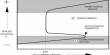
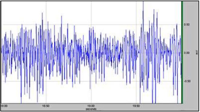
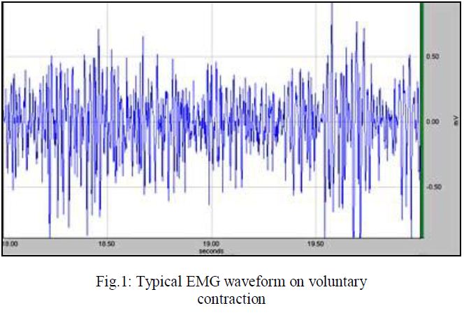
The body is a volume conductor, consisting of electrolytes, having both positive and negative free ions. Therefore, within the body the dipole vectors give rise to an external current which change with time. When a current flows through a resistor, a potential drop occurs across it. Similarly due to the external current distribution in the volume conductor, potential differences are produced between any two points. This potential difference can be picked up using two electrodes placed at two suitable points outside, which when plotted against time gives the well known EMG as shown in Fig.1.
A metallic electrode connected to a mass of electrolyte such as the human body contributes to a dc contact potential of the order of a volt. Since both electrodes are usually of the same metal, the dc contact potentials have opposite directions in the circuit loop which should cancel out ideally. This cancellation is not total and some low frequency ac potential may be present due to differences in slow acting chemical reactions under the two electrodes. However, since EMG is an ac greater than 10Hz, the dc or the low frequency potentials may be eliminated using an appropriate high pass filter, which has indeed been done inside the EMG amplifier.
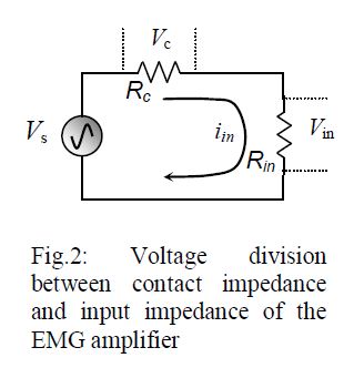
The contact impedance for skin surface electrodes is also important as discussed with the help of Fig.2. When connected to the input of an amplifier, the source voltage vs (EMG here) is dropped across both the contact impedance Rc and the input impedance Rin of the amplifier. We want Rc << Rin such that almost the whole of the source voltage is dropped across Rin. Besides, due to ground loop currents, some mains ac may be dropped across these contact impedances increasing the 50Hz noise as explained in the next section. Therefore, we have to take care that the contact impedances are minimum. This is very important for the ‘Common’ electrode which has a greater contribution to common mode 50Hz noise. Therefore, the common electrode is usually made of larger contact area compared to the active potential pick-up electrodes. Typically the contact impedances vary from about 5kΩ to about 50 kΩ at low frequencies depending on the metal type and the skin preparation. Human skin surface is composed of dead horny cells contributing to large impedance. Besides, there may be oil or grease increasing the impedance further. Therefore, before electrodes are applied, the skin should be rubbed well using alcohol, preferably with some fine abrasive to remove the dead cells, and conduction electrode gel should be applied to the electrodes before attaching to the skin.
Interference and noise, necessity of differential amplifier & filters
EMG is usually associated with a large noise voltage, mostly from the mains electrical lines at 50Hz (60 Hz in some countries). How this noise gets through is explained below.
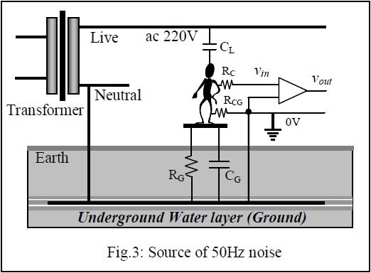
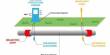
The main source of noise in an EMG equipment is the 50Hz mains. Fig.3 shows how it gets into an amplifier. At the street poles, the transformer that supplies 220V to our premises, one of the secondary terminals is connected to the underground water layer, the Ground of our electrical system. The underground water layer can be considered to be a good conductor of electricity and is the common Ground for all appliances and circuit connections. This ground connected secondary terminal is called the Neutral indicating that if we touch it while standing on the ground we would not get a shock since there is no electrical potential difference between the two points of touch. On the other hand if we touch the other secondary terminal, called the Live, while standing on the ground, we will get a shock since we will be in between a 220V ac potential.
Our body has two electrical connections to the Ground, a very high resistance RG, which is the leakage path from our body to the Ground, and a capacitance CG in parallel. There is also a capacitance CL between our body and the Live terminal. In this electrical system, our body, full of electrolytes, acts as a conductor with low impedance. Now CL and CG (with RG in parallel to the latter) form a voltage divider and therefore without any other electrical connections, our body is at a substantial 50Hz potential (typically 20V) with respect to the Ground. The live wire is not only in the house wiring, it comes to equipment that we are handling, and therefore is quite close to us. Depending on the proximity of the live wire, we can have tens of volts of 50Hz ac on our body, which can be perceived when we touch the tip of an oscilloscope probe without touching the ground.
At our premises a third connection is brought out, side by side to the two mains ac lines, by placing a metallic plate or rod deep into the ground. The idea is that it will connect to the underground water layer (which is actually done so in large buildings through ground boring, but not so in smaller constructions), and this is the third connection in a 3-pin mains socket, called the Earth or Ground connection. If an electrode is attached to our body which is directly connected to the ground point, a contact resistance RCG at the electrode skin interface comes into play which is relatively small, and the 50Hz ac potential on our body drops to a low value (voltage dropped across RCG). If an EMG electrode is connected with a good skin preparation, RCG can be of the order of 10kΩ and the 50Hz potential on the body, with respect to the ground, comes down to about 10 or 20 millivolts. This is low, but not so when we compare with the EMG signal which is only about 0.5mV in amplitude. So if we want to detect EMG signal using an electrode at any point on our body (where the contact resistance has been shown to be RC) and connect it to the input of a normal single ended amplifier (having one input), the net input signal vin will consist of both the EMG signal (~0.5mV) and the 50Hz noise (~10mV) dropped across RCG. It is easy to see that the noise is about 20 times larger and it will be impossible to discern the EMG signal under such a situation. Besides, the frequency content of EMG picked up using skin surface electrodes is approximately between 10Hz and 3000 Hz, so filtering out such a large 50Hz signal will distort the EMG signal itself. Therefore normal amplifiers with one input port that are used in most normal applications, such as in radio and audio applications, cannot be used to amplify bioelectrical signals like EMG.
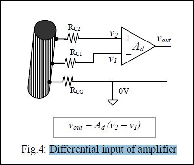
Fortunately, this noise voltage is almost the same all over the body since the body resistance is very small compared to series reactances and resistances in the 50Hz current loop. Therefore a differential amplifier may be used to eliminate this noise. This amplifier has two inputs with respect to a common terminal (0V reference), and the output is proportional to the difference of the two inputs, as shown in Fig.4. The two input terminals are connected to electrodes placed at two points on the muscle mass while a third electrode, placed at any other point on the body, is taken as the common terminal. Since the 50Hz noise has the same amplitude at both the input electrodes with respect to the common terminal as mentioned above, on subtraction this noise is eliminated while the difference signal, which is the EMG in this case, appears at the output, amplified through a differential voltage gain of Ad. The same 50Hz noise appearing at both the inputs is known as the Common Mode signal (vcm). Ideally the common mode signal should get totally eliminated in a differential amplifier, and the relationship is expected to be,
Vout = Ad (V2 – V1). … … (1)
Practically the common mode signal cannot be totally eliminated, a small non-zero common mode voltage gain Acm is present and the equation is modified as,
Vout = Ad (V2 – V1) + Acm Vcm … … (2)
We would want Acm to be as small as possible with respect to Ad. The ratio of Ad to Acm is defined as the Common Mode Rejection Ratio (CMRR), i.e.,
CMRR = Ad/Acm … … (3)
Obviously we would want CMRR to be as large as possible. Usually it is expressed in dB units given by,
CMRR = 20 log Ad/Acm … … (4)
The 50Hz common mode noise needs to be reduced to about one hundredth of the maximum size of the signal, i.e., about 0.005mV for EMG. That is, a 10mV 50Hz noise has to be effectively reduced by 2000 times (or by 63dB).
There is a safety aspect necessary with all hospital based electrical equipment. In hospitals there may be situations where catheters are connected directly to heart muscles. If a small current, of the order of 50μA at 50Hz passes through such a directly connected electrode, the heart may go into a state called defibrillation in which the rhythmic contraction is lost, resulting in loss of blood being pumped, causing eventual death. This is called ‘microshock’ in contrast to normal shock that we receive by touching a mains live cable by hand, where the dry skin provides a large resistance (about 30kΩ) limiting the current. Besides, the current distributes throughout the body having only a minute fraction passing through the heart itself. Thus in such a situation about 75mA (more than 1000 times the microshock value) is needed to cause defibrillation and death. Although most patients in hospitals do not have a catheter connected to their heart, we cannot take risk even if one patient out of a thousand have this dangerous situation. Therefore, all circuitry connected to the patient should be electrically isolated from the mains connected equipment such that not more than 10μA passes through the patient even in case the live 220V wire gets shorted to the body (ground) or to any other circuit part of the mains connected equipment. There is another source of noise voltage. Since the EMG amplifier has to be connected to an oscilloscope or a computer which is driven by mains 50Hz, through capacitive coupling this 50Hz noise gets into the input of the amplifier. The EMG amplifier supplied has been designed to tackle the above problems.
The Experiment, Methods and Measurements
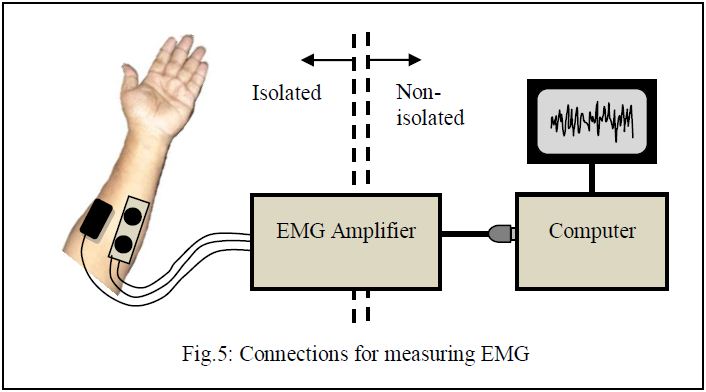
Fig.5 shows the way to connect the EMG amplifier to a human subject on one side, and to a computer on the other through its USB port. The pad with two active electrodes is to be placed on the belly of a muscle, along its length, while the larger common electrode should be connected nearby at any point, preferably at a point at almost equal distances from the two active electrodes. It is better to keep the common electrode away from places with fatty layers underneath, because fat layers will increase the electrode impedance.
Prepare the skin well by rubbing with an anti-greasing agent like alcohol (liquid Savlon may do) with a mild abrasive pad, like a strong tissue paper. Let it dry. Now put a drop of electrode jel onto the electrodes each and attach them to the hand muscle as shown using a Velcro strap supplied.
Run the EMG programme on the computer and click on to the ‘EMG’ tab. Most instructions will be available on-screen as you go through the steps. You will see a display of several seconds duration in the graphical window.
With the hand muscles relaxed try to see that you get an almost flat response. You may get a periodical 50Hz noise. Try to move yourself away from the table or other equipment as much as possible, you will find a minimum of this noise at a certain arrangement.
Now grip your fingers into a strong fist. You may try holding a cylindrical object of about 3cm diameter. You will see the EMG signal on the screen. Get an estimate of the average maximum amplitude using a plastic scale placed on the screen. Now reduce the strength of the grip and again measure the average maximum amplitude. Note the values. You may fix the electrodes on other muscles (getting information from an anatomy book) and see differences, if any. Now do the same with another subject, note the values and see the difference with yours. Of course here you do not have a measure of the gripping force, but instruments are available that can measure such forces.
Results and Presentations
Make a table with one column showing average maximum amplitude on light contraction and another column showing that for strong contraction. Do this for several subjects and enter these in different rows. You may similarly make another table for EMG from different muscles from the same subject.
Discussions
The discussion should be separated into three sections, on theory and assumptions, on methods and experiments, and on the results, but without any headings.
Under the first section you may include the following:
1. EMG obtained using surface electrodes give a gross evaluation of a whole muscle mass. The signal picked up is a combination of action potentials of all the fibres in the contracted muscle, however, the ones nearer to the electrodes contribute more.
2. Surface EMG may also be used to assess the strength of contraction. This may be useful to assess the recovery of stroke patients.
3. Surface EMG may also be used to monitor activity of babies.
4. Surface EMG from muscles on the face may be used to control equipment, wheel chair, etc. by paralysed patients.
Under the second section you may include the following:
1. Skin should be adequately prepared to get low values of contact impedances under the electrodes, otherwise 50Hz noise will increase.
2. Electrode conducting gel should be used carefully, If these spread out beyond the electrodes, there is a chance that the gel will create a shorting path on the skin, thus reducing the EMG significantly. If the electrode is repositioned, the gel on the skin due to the previous placement should be wiped off with alcohol or savlon and dried.
3. If you get large 50Hz noise check the electrode contacts, sit away from any table on which other electrical equipment are placed. Try to move away from any mains cable, or wires that are from the mains connected ‘non-isolated’ side.
4. You may try sitting on a wooden chair instead of a chair with a metallic frame to see if it reduces noise.
Under the third section you may include the following:
1. EMG gives an insight to our body electricity.
2. Amplitude of EMG increases with increased contraction of muscle.
3. Amplitude of EMG will depend on muscle mass, a muscle with more mass may give larger EMG signals. A person with more muscle mass may give a higher EMG as well.
4. EMG signals can further be analysed to show average, cumulative integration, frequency spectrum, etc. to compare healthy muscles from ones with disorders.