INTRODUCTION OF GAS:
1. Gas
This page is about the physical properties of gas as a state of matter. For the uses of gases, and other meanings, see Gas disambiguation.
Gas phase particles atoms, molecules, or ions move around freely
A gas is a state of matter, consisting of a collection of particles molecules, atoms, ions, electrons, etc. without a definite shape or volume that are in more or less random motion
Physical characteristics
Due to the electronic nature of the aforementioned particles, a “force field” is present throughout the space around them. Interactions between these “force fields” from one particle to the next give rise to the term intermolecular forces. Dependent on distance, these intermolecular forces influence the motion of these particles and hence their thermodynamic properties. It must be noted that at the temperatures and pressures characteristic of many applications, these particles are normally greatly separated. This separation corresponds to a very weak attractive force. As a result, for many applications, this intermolecular force becomes negligible.
A gas also exhibits the following characteristics:
- Relatively low density and viscosity compared to the solid and liquid states of matter.
- Will expand and contract greatly with changes in temperature or pressure, thus the term “compressible”.
- Will diffuse readily, spreading apart in order to homogeneously distribute itself throughout any container.
Macroscopic:
When analyzing a system, it is typical to specify a length scale. A larger length scale may correspond to a macroscopic view of the system, while a smaller length scale corresponds to a microscopic view.
On a macroscopic scale, the quantities measured are in terms of the large scale effects that a gas has on a system or its surroundings such as its velocity, pressure, or temperature. Mathematical equations, such as the extended hydrodynamic equations, Nervier-Stokes equations and the Euler equations have been developed to attempt to model the relations of the pressure, density, temperature, and velocity of a moving gas.
Pressure:
The pressure exerted by a gas uniformly across the surface of a container can be described by simple kinetic theory. The particles of a gas are constantly moving in random directions and frequently collide with the walls of the container and/or each other. These particles all exhibit the physical properties of mass, momentum, and energy, which all must be conserved. In classical mechanics, Momentum, by definition, is the product of mass and velocity. Kinetic energy is one half the mass multiplied by the square of the velocity.
The sum of all the normal components of force exerted by the particles impacting the walls of the container divided by the area of the wall is defined to be the pressure. The pressure can then be said to be the average linear momentum of these moving particles. A common misconception is that the collisions of the molecules with each other is essential to explain gas pressure, but in fact their random velocities are sufficient to define this quantity
Temperature:
The temperature of any physical system is the result of the motions of the molecules and atoms which make up the system. In statistical mechanics, temperature is the measure of the average kinetic energy stored in a particle. The methods of storing this energy are dictated by the degrees of freedom of the particle itself (energy modes). These particles have a range of different velocities, and the velocity of any single particle constantly changes due to collisions with other particles. The range in speed is usually described by the Maxwell-Boltzmann distribution.
Specific Volume:
When performing a thermodynamic analysis, it is typical to speak of intensive and extensive properties. Properties which depend on the amount of gas are called extensive properties, while properties that do not depend on the amount of gas are called intensive properties. Specific volume is an example of an intensive property because it is the volume occupied by a unit of mass of a material, meaning we have divided through by the mass in order to obtain a quantity in terms of, for example, Notice that the difference between volume and specific volume differ in that the specific quantity is mass independent.
Density:
Because the molecules are free to move about in a gas, the mass of the gas is normally characterized by its density. Density is the mass per volume of a substance or simply, the inverse of specific volume. For gases, the density can vary over a wide range because the molecules are free to move. Macroscopically, density is a state variable of a gas and the change in density during any process is governed by the laws of thermodynamics. Given that there are many particles in completely random motion, for a static gas, the density is the same throughout the entire container. Density is therefore a scalar quantity; it is a simple physical quantity that has a magnitude but no direction associated with it. It can be shown by kinetic theory that the density is proportional to the size of the container in which a fixed mass of gas is confined.
Microscopic:
On the microscopic scale, the quantities measured are at the molecular level. Different theories and mathematical models have been created to describe molecular or particle motion. A few of the gas-related models are listed below.
Kinetic theory
Kinetic theory attempts to explain macroscopic properties of gases by considering their molecular composition and motion.
Brownian motion:
Brownian motion is the mathematical model used to describe the random movement of particles suspended in a fluid often called particle theory.
Since it is at the limit of (or beyond) current technology to observe individual gas particles (atoms or molecules), only theoretical calculations give suggestions as to how they move, but their motion is different from Brownian motion. The reason is that Brownian Motion involves a smooth drag due to the frictional force of many gas molecules, punctuated by violent collisions of an individual (or several) gas molecule(s) with the particle. The particle (generally consisting of millions or billions of atoms) thus moves in a jagged course, yet not so jagged as we would expect to find if we could examine an individual gas molecule.
Intermolecular forces:
.As discussed earlier, momentary attractions (or repulsions) between particles have an effect on gas dynamics. In physical chemistry, the name given to these “intermolecular forces” is the “Vander Waals force
Simplified models:
An equation of state (for gases) is a mathematical model used to roughly describe or predict the state of a gas. At present, there is no single equation of state that accurately predicts the properties of all gases under all conditions. Therefore, a number of much more accurate equations of state have been developed for gases under a given set of assumptions. The “gas models” that are most widely discussed are “Real Gas”, “Ideal Gas” and “Perfect Gas”. Each of these models have their own set of assumptions to, basically, make our lives easier when we want to analyze a given thermodynamic system.
Real gas:
Real gas effects refer to an assumption base where the following are taken into account:
- Compressibility effects
- Variable heat capacity
- Vander Waal forces
- Non-equilibrium thermodynamic effects
- Issues with molecular dissociation and elementary reactions with variable composition.
For most applications, such a detailed analysis is excessive. An example where “Real Gas effects” would have a significant impact would be on the Space Shuttle re-entry where extremely high temperatures and pressures are present
Ideal gas:
An “ideal gas” is a simplified “real gas” with the assumption that the compressibility factor Z is set to 1. So the state variables follow the law. This approximation is more suitable for applications in engineering although simpler models can be used to produce a “ball-park” range as to where the real solution should lie. An example where the “ideal gas approximation” would be suitable would be inside a combustion chamber of a jet engine. It may also be useful to keep the elementary reactions and chemical dissociations for calculating emissions.
Perfect gas:
By definition, A perfect gas is one in which intermolecular forces are neglected. So, along with the assumptions of an Ideal Gas, the following assumptions are added
By neglecting these forces, the equation of state for a perfect gas can be simply derived from kinetic theory or statistical mechanics.
This type of assumption is useful for making calculations very simple and easy to do. With this assumption we can apply the Ideal gas law without restriction and neglect many complications that may arise from the Vander Waals forces.
Along with the definition of a perfect gas, there are also two more simplifications that can be made although various textbooks either omit or combine the following simplifications into a general “perfect gas” definition. For sake of clarity, these simplifications are defined separately.
Natural gas:
Natural gas is a gaseous fossil fuel consisting primarily of methane but including significant quantities of ethane, propane, butane, and pentane—heavier hydrocarbons removed prior to use as a consumer fuel —as well as carbon dioxide, nitrogen, helium and hydrogen sulfide. It is found in oil fields (associated) either dissolved or isolated in natural gas fields (non associated), and in coal beds (as coaled methane). When methane-rich gases are produced by the anaerobic decay of non-fossil organic material, these are referred to as biogas. Sources of biogas include swamps, marshes, and landfills (see landfill gas), as well as sewage sludge and manure by way of anaerobic digesters, in addition to enteric fermentation particularly in cattle.
Since natural gas is not a pure product, when non associated gas is extracted from a field under supercritical (pressure/temperature) conditions, it may partially condense upon isothermal depressurizing–an effect called retrograde condensation. The liquids thus formed may get trapped by depositing in the pores of the gas reservoir. One method to deal with this problem is to reinvest dried gas free of condensate to maintain the underground pressure and to allow evaporation and extraction of condensates.
Natural gas is often informally referred to as simply gas, especially when compared to other energy sources such as electricity. Before natural gas can be used as a fuel, it must undergo extensive processing to remove almost all materials other than methane. The by-products of that processing include ethane, propane, butanes, pentanes and higher molecular weight hydrocarbons, elemental sulfur, and sometimes helium and nitrogen.
Chemical composition:
The primary component of natural gas is methane (CH4), the shortest and lightest hydrocarbon molecule. It often also contains heavier gaseous hydrocarbons such as ethane (C2H6), propane (C3H8) and butane (C4H10), as well as other sulfur containing gases, in varying amounts, see also natural gas condensate. Natural gas that contains hydrocarbons other than methane is called wet natural gas. Natural gas consisting only of methane is called dry natural gas.
| Component | Typical wt. % |
| Methane (CH4) | 70-90 |
| Ethane (C2H6) | 5-15 |
| Propane (C3H8) and Butane (C4H10) | < 5 |
| CO2, N2, H2S, etc. | balance |
Nitrogen, helium, carbon dioxide and trace amounts of hydrogen sulfide, water and odorants can also be present Natural gas also contains and is the primary market source of helium. Mercury is also present in small amounts in natural gas extracted from some fields The exact composition of natural gas varies between gas fields.
Organ sulfur compounds and hydrogen sulfide are common contaminants which must be removed prior to most uses. Gas with a significant amount of sulfur impurities, such as hydrogen sulfide, is termed sour gas; gas with sulfur or carbon dioxide impurities is acid gas. Processed natural gas that is available to end-users is tasteless and odorless, however, before gas is distributed to end-users, it is odorized by adding small amounts of odorants (mixtures of t-butyl merchantman, isopropyl mercaptanthiol, tetrahydrothiophene, diethyl sulfide and other sulfur compounds), to assist in leak detection. Processed natural gas is, in itself, harmless to the human body, however, natural gas is a simple asphyxiate and can kill if it displaces air to the point where the oxygen content will not support life.
Natural gas can also be hazardous to life and property through an explosion. Natural gas is lighter than air, and so tends to escape into the atmosphere. But when natural gas is confined, such as within a house, gas concentrations can reach explosive mixtures and, if ignited, result in blasts that could destroy buildings. Methane has a lower explosive limit of 5% in air, and an upper explosive limit of 15%. Explosive concerns with compressed natural gas used in vehicles are almost non-existent, due to the escaping nature of the gas, and the need to maintain concentrations between 5% and 15% to trigger explosions.
| 2.Combined Cycle Power Plan
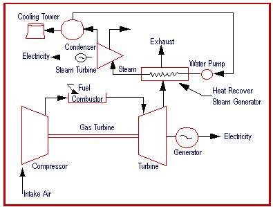
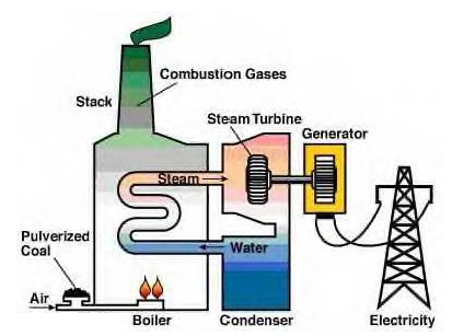
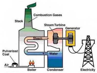
The combined-cycle unit combines the Rankin (steam turbine) and Breton (gas turbine) thermodynamic cycles by using heat recovery boilers to capture the energy in the gas turbine exhaust gases for steam production to supply a steam turbine as shown in the figure “Combined-Cycle Cogeneration Unit”. Process steam can be also provided for industrial purposes. A combined cycle is characteristic of a power producing engine or plant that employs more than one thermodynamic cycle. Heat engines are only able to use a portion of the energy their fuel generates (usually less than 50%). The remaining heat from combustion is generally wasted. Combining two or more “cycles” such as the Brayton cycle and Rankine cycle results in improved overall efficiency. In a combined cycle power plant (CCPP), or combined cycle gas turbine (CCGT) plant, a gas turbine generator generates electricity and the waste heat is used to make steam to generate additional electricity via a steam turbine; this last step enhances the efficiency of electricity generation. Most new gas power plants in North America and Europe are of this type. In a thermal power plant, high-temperature heat as input to the power plant, usually from burning of fuel, is converted to electricity as one of the outputs and low-temperature heat as another output. As a rule, in order to achieve high efficiency, the temperature difference between the input and output heat levels should be as high as possible (see Carnot efficiency). This is achieved by combining the Rankine (steam) and Brayton (gas) thermodynamic cycles. Such an arrangement used for marine propulsion is called Combined Gas (turbine) And Steam (turbine) (COGAS). Working principle of a combined cycle power plant: In a thermal power station water is the working medium. High pressure steam requires strong, bulky components. High temperatures require expensive alloys made from nickel or cobalt, rather than inexpensive steel. These alloys limit practical steam temperatures to 655 °C while the lower temperature of a steam plant is fixed by the boiling point of water. With these limits, a steam plant has a fixed upper efficiency of 35 to 42%. An open circuit gas turbine cycle has a compressor, a combustor and a turbine. For gas turbines the amount of metal that must withstand the high temperatures and pressures is small, and less expensive materials can be used. In this type of cycle, the input temperature to the turbine (the firing temperature), is relatively high (900 to 1,350 °C). The output temperature of the flue gas is also high (450 to 650 °C). This is therefore high enough to provide heat for a second cycle which uses steam as the working fluid; (a Rankine cycle). In a combined cycle power plant, the heat of the gas turbine’s exhaust is used to generate steam by passing it through a heat recovery steam generator (HRSG) with a live steam temperature between 420 and 580 °C. The condenser of the Rankine cycle is usually cooled by water from a lake, river, sea or cooling towers. This temperature can be as low as 35 °C
Fossil fuel-fired (central) power plants use either steam or combustion turbines to provide the mechanical power to electrical generators. Pressurized high temperature steam or gas expands through various stages of a turbine, transferring energy to the rotating turbine blades. The turbine is mechanically coupled to a generator, which produces electricity. Steam Turbine Power Plants: Steam turbine power plants operate on a Rankin cycle. The steam is created by a boiler, where pure water passes through a series of tubes to capture heat from the firebox and then boils under high pressure to become superheated steam. The heat in the firebox is normally provided by burning fossil fuel (e.g. coal, fuel oil or natural gas). However, the heat can also be provided by biomass, solar energy or nuclear fuel. The superheated steam leaving the boiler then enters the steam turbine throttle, where it powers the turbine and connected generator to make electricity. After the steam expands through the turbine, it exits the back end of the turbine, where it is cooled and condensed back to water in the surface condenser. This condensate is then returned to the boiler through high-pressure feed pumps for reuse. Heat from the condensing steam is normally rejected from the condenser to a body of water, such as a river or cooling tower. Steam turbine plants generally have a history of achieving up to 95% availability and can operate for more than a year between shutdowns for maintenance and inspections. Their unplanned or forced outage rates are typically less than 2% or less than one week per year. Modern large steam turbine plants (over 500 MW) have efficiencies approaching 40-45%. These plants have installed costs between $800 and$2000/kW, depending on environmental permitting requirements.
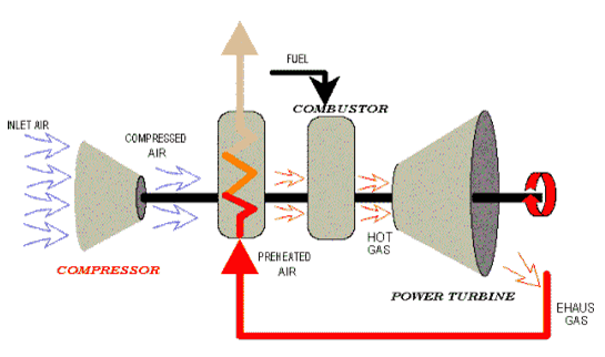
Combustion turbine plants operate on the Brayton cycle. They use a compressor to compress the inlet air upstream of a combustion chamber. Then the fuel is introduced and ignited to produce a high temperature, high-pressure gas that enters and expands through the turbine section. The turbine section powers both the generator and compressor. Combustion turbines are also able to burn a wide range of liquid and gaseous fuels from crude oil to natural gas. The combustion turbine’s energy conversion typically ranges between 25% to 35% efficiency as a simple cycle. The simple cycle efficiency can be increased by installing a recuperate or waste heat boiler onto the turbine’s exhaust. A recuperate captures waste heat in the turbine exhaust stream to preheat the compressor discharge air before it enters the combustion chamber. A waste heat boiler generates steam by capturing heat form the turbine exhaust. These boilers are known as heat recovery steam generators (HRSG). They can provide steam for heating or industrial processes, which is called cogeneration. High-pressure steam from these boilers can also generate power with steam turbines, which is called a combined cycle (steam and combustion turbine operation). Recuperates and HRSGs can increase the combustion turbine’s overall energy cycle efficiency up to 80%. Combustion (natural gas) turbine development increased in the 1930’s as a means of jet aircraft propulsion. In the early 1980’s, the efficiency and reliability of gas turbines had progressed sufficiently to be widely adopted for stationary power applications. Gas turbines range in size from 30 kW (micro-turbines) to 250 MW (industrial frames). Industrial gas turbines have efficiencies approaching 40% and 60% for simple and combined cycles respectively. The gas turbine share of the world power generation market has climbed from 20 % to 40 % of capacity additions over the past 20 years with this technology seeing increased use for base load power generation. Much of this growth can be accredited to large (>500 MW) combined cycle power plants that exhibit low capital cost (less than $550/kW) and high thermal efficiency. The capital cost of a gas turbine power plant can vary between $35000-$950/kW with the lower end applying to large industrial frame turbines in combined cycle configurations. Availability of natural gas-fired plants can exceed 95%. In Canada, there are 28 natural gas-fired combined cycle and cogeneration plants with an average efficiency of 48 %. The average power output for each plant was 236 MW with an installed cost of around $ 500/kW.
Simple Cycle Power Plants (Open Cycle): The modern power gas turbine is a high-technology package that is comprised of a compressor, combustor, power turbine, and generator, as shown in the figure “Simple-Cycle Gas Turbine”. In a gas turbine, large volumes of air are compressed to high pressure in a multistage compressor for distribution to one or more combustion gases from the combustion chambers power an axial turbine that drives the compressor and the generator before exhausting to atmosphere. In this way, the combustion gases in a gas turbine power the turbine directly, rather than requiring heat transfer to a water/steam cycle to power a steam turbine, as in the steam plant. The latest gas turbine designs use turbine inlet temperatures of 1,500C (2,730F) and compression ratios as high as 30:1 (for aero derivatives) giving thermal efficiencies of 35 percent or more for a simple-cycle gas turbine. Brayton cycle The Brayton cycle is a constant-pressu that describes the workings of the gas turbine engine, basis of the jet engine and others. It is named after George Brayton (1830–1892), the American engineer who developed it, although it was originally proposed by Barber in 1791. It is also sometimes known as the Joule cycle. The Ericsson cycle is also similar but uses external heat and incorporates the use of a regenerator Like other internal combustion power cycles, The Brayton cycle is an open system, though for thermodynamic analysis it is conventionally assumed that the exhaust gases are reused in the intake, enabling analysis as a closed system. Since neither the compression nor the expansion can be truly isentropic, losses through the compressor and the expander represent sources of inescapable working inefficiencies. In general, increasing the compression ratio is the most direct way to increase the overall power output of a Brayton system. Here are two plots, Figure 1 and Figure 2, for the ideal Brayton cycle. One plot indicates how the cycle efficiency changes with an increase in pressure ratio, while the other indicates how the specific power output changes with an increase in the gas turbine inlet temperature for two different pressure ratio values. A Brayton-type engine consists of three components:
In the original 19th-century Brayton engine, ambient air is drawn into a piston compressor, where it is compressed; ideally an isentropic process. The compressed air then runs through a mixing chamber where fuel is added, a constant-pressure isobaric process. The heated (by compression), pressurized air and fuel mixture is then ignited in an expansion cylinder and energy is released, causing the heated air and combustion products to expand through a piston/cylinder; another theoretically isentropic process. Some of the work extracted by the piston/cylinder is used to drive the compressor through a crankshaft arrangement. Ideal Brayton cycle:
Actual Brayton cycle:
Since neither the compression nor the expansion can be truly isentropic, losses through the compressor and the expander represent sources of inescapable working inefficiencies. In general, increasing the compression ratio is the most direct way to increase the overall power output of a Brayton system. Here are two plots, Figure 1 and Figure 2, for the ideal Brayton cycle. One plot indicates how the cycle efficiency changes with an increase in pressure ratio, while the other indicates how the specific power output changes with an increase in the gas turbine inlet temperature for two different pressure ratio values. In 2002 a hybrid open solar Brayton cycle was operated for the first time consistently and effectively with relevant papers published, in the frame of the EU SOLGATE program. The air was heated from 570 K to over 1000 K into the combustor chamber. Methods to increase power: The power output of a Brayton engine can be improved in the following manners:
Methods to improve efficiency: The efficiency of a Brayton engine can be improved in the following manners:
Reverse Brayton cycle: A Brayton cycle that is driven in reverse, via net work input, and when air is the working fluid, is the air refrigeration cycle or Bell Coleman cycle. Its purpose is to move heat, rather than produce work. This air cooling technique is used widely in jet aircraft.
|
Gasturbineefficiency:
Gas turbines form the base of many cogeneration systems, so the efficiency of the turbine is fundamental to the efficiency of the overall plant.
A gas turbine functions by allowing the passage of expanding combustion gases through a series of turbine blades (see Figures 1 and 2). The efficiency of the turbine is measured by comparing power input to power output as measured by mechanical energy in the output shaft. Gas turbine efficiencies are usually given for ISO conditions at 15°C, 60% relative humidity and an atmospheric pressure equivalent to average sea level conditions. Variations in temperatures and relative humidities during operation of the turbine will result in changes to its efficiency
The efficiency of a gas turbine – more correctly called the overall thermal efficiency – is the ratio of work done to the heat supplied. Efficiency is defined as:
Efficiency = 100 x K x (Tmax – Tmin)/Tmax
Tmax is the temperature of the gas at the inlet to the gas turbine, Tmin is the ambient temperature and K is internal losses.
As a result, there are three theoretical methods of increasing efficiency: increasing inlet temperature, decreasing ambient temperature and reducing internal losses.
Theoretically, a gas turbine could achieve efficiencies of up to 65%. At present, simple open-cycle turbines achieve efficiencies of about 40%. In addition, it is possible to use waste heat from the outlet of the gas turbine to improve efficiency of use. This is where the very high overall efficiencies from cogeneration come from.
Figure: 4.1.3 Idealized gas turbine heat cycle
The basic gas turbine cycle is shown in Figure 3. Air is compressed from point 1 to point 2. This increases the pressure as the volume of space occupied by the air is reduced. The air is then heated at constant pressure from point 2 to point 3. This heat is added by injecting fuel into the combustor and continuously igniting it. The hot compressed air at point 3 is then allowed to expand (point 3 to point 4), reducing the pressure and temperature and increasing the volume. This represents flow through the turbine to point 3’ and then flow through the power turbine to point 4. The combustion cycle is completed by decreasing the volume of air (point 4 to point 1) through decreasing the temperature, with heat being absorbed into the atmosphere.
This cycle is the simple gas turbine cycle, called the Brayton cycle. However, additional equipment and techniques can be used to increase the efficiency of the cycle. These modifications include: regeneration, inter cooling and reheating.
In general, efficiency influenced by:
- energy used by the air compressor – if less energy is used to compress the air, more energy is available at the output shaft
- temperature of the gas leaving the combustors and entering the turbine – the higher the temperature, the greater the efficiency
- temperature of the exhaust gas from the turbine – the lower the temperature, the greater the efficiency
- mass flow through the gas turbine – in general, higher mass flows result in higher efficiencies
- pressure drop across inlet air filters – increased pressure loss decreases efficiency
- pressure drop across exhaust gas silencers, ducts and stack – increased pressure loss decreases efficiency.
There has been considerable work done to improve the efficiency of gas turbines, mainly on increasing turbine entrygas temperatures and increasing the efficiency and capability of the compressor. Various methods have been used to improve efficiency in these areas. These include:
- using the exhaust gas to heat the air from the compressor – this is most effective in cold weather
- dividing the compressor into two parts and cooling the air between the two parts
- dividing the turbine into two parts and reheating the gas between the two parts
- cooling the inlet air – this is mainly used in hot weather
- reducing the humidity of the inlet air
- increasing the pressure of the air at the discharge of the air compressor
- Regularly washing or otherwise cleaning the fouling of turbine and air-compressor blades.
However, there is a trade-off with all of these methods of increasing efficiency. They all increase costs, and some reduce the available power output of the gas turbine. The final design choice will be the most appropriate compromise that balances cost, power and efficiency for each specific application.
These different approaches can be broken down into five main categories:
- increased inlet temperature
- regeneration
- compressor intercooling
- turbine reheat
- steam/water injection.
Increasing turbine inlet temperature
(OPRA Gas Turbines):
The most obvious way of increasing the efficiency of a gas turbine is to increase the inlet temperature. Efficiency is related to both the inlet and outlet temperatures of the turbine; the higher the difference between the two temperatures, the greater the thermal efficiency of the turbine. There is an absolute limit to how low the outlet temperature can go, so increasing the inlet temperature is an obvious method of increasing efficiency.
However, increases in inlet temperature have already reached the point where the temperatures are actually higher than the melting point of some of the metals used in the turbine. Cooling of the first rows of turbine blades is therefore imperative, and any further increases in inlet temperature will require improvements in cooling techniques. This could involve increased use of steam cooling, increased flow of the cooling fluid, or increased effectiveness of heat transfer with the cooling fluid.
In addition, different materials with improved heat-resisting properties and improved thermal barrier coating can also assist in allowing the elevation of the inlet temperature.
Nonetheless, the cost involved in increasing the efficiency of the turbine through raising the inlet temperature is becoming increasingly prohibitive. The materials involved are adding to the cost, while the addition of ever-more complex cooling techniques gives rise to more expensive production and more areas that need maintenance, which adds to O&M costs. It also introduces more items that can fail, potentially leading to greater outage time for the turbine.
The pressure ratio has to be increased alongside increases in turbine inlet temperature otherwise the turbine exit temperature will drop, resulting in a reduction in the combined cycle efficiency.
Regeneration:
Regeneration is the internal exchange of heat within the cycle. In the gas turbine cycle, the gases leaving the turbine are at a relatively high temperature. This temperature is higher than the temperature at the compressor outlet. Therefore, a regenerator (a surface-type heat exchanger) is used to preheat the compressed gases by using heat from the exhaust gas. This reduces the amount of fuel required by the combustor. Regeneration involves the installation of a heat exchanger (recuperator) through which the turbine exhaust gases pass. The compressed air is then heated in the exhaust gas heat exchanger before the flow enters the combustor, preheating the gas before it enters the combustion chamber, thus reducing the amount of fuel required (see Figure 4).
Use of a regenerator can increase the simple-cycle efficiency. However, the relatively high cost of such a regenerator is a disincentive to its use. Regeneration can improve the efficiency of simple gas turbines by 5%–6%. However, use of a regenerator reduces specific power output as a result of additional pressure losses in the regenerator.
According to the Managing Director of OPRA Gas Turbines, Frederick Mowill, gas turbines have exit temperatures of about 560°C. This heat can be of great use in providing energy to produce process steam or heating. The use of a recuperator reduces this exit temperature to about 330°C. As a result, while the efficiency of the gas turbine is increased by the use of a recuperator, the available energy from the heat of the gas exhaust is reduced. Operators have to decide which is more important for their specific needs.
Compressor intercooling:
Another method of increasing the overall efficiency of a gas turbine is to decrease the work input to the compression process. The effect of this is to increase the net work output. This can be achieved by cooling the gas passing through the compressor. Intercooling involves compressing the fluid to an intermediate pressure, then passing it through a heat exchanger, or intercooler, where it is cooled to a lower temperature at essentially constant pressure. The fluid is then passed through another stage of the compressor, where its pressure is increased. This is followed by another intercooler process, and then another staging of the compressor, until the final pressure is achieved (see Figure 5). The overall result is a lowering of the net work input required for a given pressure ratio.
Intercoolers can be air-cooled heat exchangers but are more commonly water-cooled. The output of a gas turbine is increased with an intercooler.
Turbine reheat:
Another method of increasing overall efficiency is to keep the gas temperature in the turbine as high as possible. This can be achieved by continuous heating of the gas as it expands through the turbine. Continuous heating as such is not practical, and reheat is carried out in stages (see Figure 6). Gases are allowed to partially expand before being returned to the combustion chamber, where heat is added at constant pressure until the limiting temperature is reached. The use of reheat increases the turbine work output without changing the compressor work or the maximum limiting temperature. Using the turbine reheat increases the whole cycle output. However, the final turbine exhaust temperature is above the outlet turbine temperature without reheat. As a consequence, reheating is most effective when used in conjunction with regeneration, as the quantity of heat exchanged in the regenerator can be greatly increased.
If a gas turbine has a high-pressure and a low-pressure turbine at the back end of the machine, a reheater, usually another combustor, can be used to reheat the flow between the two turbines, giving an increase in efficiency of 1%–3%.
Injection of steam or water:
Steam or water injection is a method by which the output power of a gas turbine cycle can be increased. This has several effects: it increases the flexibility of the gas turbine during part load operations and significantly decreases emissions of carbon monoxide and unburned hydrocarbons.
Steam injection can be carried out using saturated or superheated steam. The introduced steam is usually injected into the combustion chamber. However, water injection is a more common method of increasing efficiency than steam injection. Water is typically injected into the system at the compressor outlet to increase the mass flow rate. The compressed air temperature falls as a consequence of water injection, but this temperature reduction can be minimized through use of a regenerator. No more fuel is consumed in this temperature compensation because the process uses heat from the gas turbine exhaust that would otherwise be wasted.
Water can also be injected at the compressor inlet. This has the following advantage compared with injection at the compressor outlet:
- Because air at the inlet air duct is at about atmospheric pressure, there is no need to use a high pressure pump.
- The inlet air temperature is atmospheric, which means there is no need to warm up the spray water to prevent thermal shock.
- There is usually a long distance between the inlet air duct and the compressor inlet, so by the time the atomized water reaches the compressor, it will be thoroughly mixed with the air, so it is a homogenized mixture of water and air that will be introduced into the compressor. This reduces impact damage and corrosion effects on compressor components.
Additional methods of increasing efficiency
Several other methods of increasing efficiency are also employed.
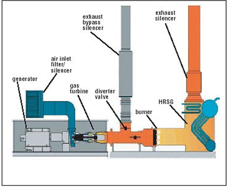
Heat recovery:
Gas turbines generate a large volume of very hot air. This exhaust is also high in oxygen content compared to other combustion exhaust streams because only a small amount of oxygen is required by the combustor relative to the total volume available. Depending on how much thermal energy is required, the turbine exhaust may be supplemented by a duct burner.
A duct burner is a direct-fired gas burner located in the turbine exhaust stream. It has a very high efficiency due to the high inlet air temperature and is used to boost the total available thermal energy. The turbine exhaust boosted by the duct burner is directed into the HRSG.
Turbine exhaust can also be ducted directly into hot air processes, such as kilns and material drying systems. This is the least costly first cost, as there is no boiler or steam drying system to purchase. Turbine exhaust can also be ducted directly into absorption chillers for large cooling loads.
The system will also include a diverter for those times when the waste heat is not required. The diverter vents the turbine exhaust to the atmosphere. This substantially reduces the system efficiency because only the electrical energy output of the turbine is being used.
The higher the electrical efficiency of the turbine the lower the available thermal energy in the exhaust. Newer turbines with recuperators and larger turbines tend to have higher efficiencies.
Inlet air cooling:
Another method of increasing turbine efficiency is through inlet air cooling. This is most effective in hot, dry climates because in effect it reduces the ambient temperature entering the turbine. Gas turbines operate with a constant volume of air, but the power generated depends on the mass flow of air. Warm air is less dense than cold air, resulting in lower power output. Warm air is also harder to compress than cold air, taking more work from the compressor and thus increasing internal losses.
Inlet air cooling is sensitive to ambient conditions at the site, and thus selection of the correct inlet air cooling system is site specific. For a typical gas turbine, it is possible to cool the inlet air from 15°C to 5.6°C, increasing fuel efficiency by about 2%.
There are many technologies that are commercially available for turbine air inlet cooling. These technologies can be divided into the following major categories:
- evaporative: wetted media, fogging and wet compression/overspray
- chillers: mechanical and absorption chillers with or without thermal energy storage
- LNG vaporization
- hybrid systems.
More details on gas turbine inlet air cooling can be found in COSPP July–August 2004.
Reduction of leakage flow:
One area of potential loss of efficiency lies in the leakage of flow through the gas turbine. This typically comes from inevitable leakage around the tips of the blades and vanes, as well as from other areas that require sealing.
Reduction of leakage is a compromise between reducing the leakage flow and allowing the leakage flow ‘necessary’ to avoid high temperature increases caused by disc friction or heat conduction or both. The most common method of optimizing blade design to achieve the best compromise is through the use of a blade tip shroud. These restrict gas leakage flow across the blade tip by using knife-edge seals designed to rub into a honeycomb seal material that is brazed onto the shroud blocks. However, centrifugal forces on the rotating stages of a gas turbine are very large. For example, an F-class blade weighing about 3.6 kg will exert a pull of over 440,000 N at operating speed. Typically, shrouds account for about 10% of the weight of a blade.
Another method of reducing flow leakage at blade tips is through the use of abradable material. The obvious method of reducing this flow leakage is to reduce the clearance between the blade tip and the casing. Reducing this clearance can result in the blade tips rubbing against the casing. By applying an abradable coating, some rubbing can be tolerated. The abradable coatings are designed to release fine wear debris while causing no wear on the blades. A balance needs to be struck between efficiency losses due to gas flow leakage and those due to friction effects.
Aerodynamic design of all components:
The optimization of the aerodynamic design of all components can help reduce internal losses. However, there is an optimization process involved. For example, reducing pressure loss in the combustor will increase efficiency but may also result in a smaller stability range. It may also influence the possibility of having efficient cooling systems, especially in the first turbine stage.
Inlet air filtration:
The operating conditions within a gas turbine can make particulate matter and chemical impurities in the air and fuel damage the blades of the turbine, either by collecting and sticking to the blades or by corroding and eroding them, which reduces their effectiveness and degrades the efficiency of the gas turbine. Consequently, the cleanliness of the air and fuel used has a major impact on the amount of maintenance required. There are two basic solutions to this: coating the turbine blades so that they can better resist this degradation; and preventing the impurities from entering the turbine in the first place.
Inlet air filtration will prevent a proportion of the impurities from entering the turbine. However, filtration also generally results in a pressure drop across the filtration system, resulting in a loss of efficiency. As a general rule, the more effective the filtration system is at removing particulate matter, the greater the pressure drop across the system and hence the greater the drop in efficiency. Designing a filtration system to maximize the first and minimize the second is a complex compromise. Precise selection will depend very heavily on site-specific operating conditions. More details on air inlet filtration can be found in COSPP March–April 2005.
Particles that stick to blades and vanes cause blade fouling. These interfere with the smooth flow of the air stream, resulting in a reduction in the mass flow through the turbine. Fouling also degrades the effective pressure ratio, also impacting on efficiency.
Fouling has to be washed away by spraying a liquid from a set of nozzles installed upstream of the inlet. The liquid follows the air stream, and mechanical movements and chemical action by the washing liquid removes the deposits. Washing can be carried out either on-line or off-line. On-line washing is not as effective as off-line washing, but has the advantage that the turbine is still generating power. On-line washing has also been criticized for causing erosion damage.
It should be noted that inlet air filtration doesn’t increase efficiency; it limits and reduces the loss of efficiency from particulate degradation.
Areas of development:
There are several areas of research being carried out with regard to aerodynamic improvements, particularly with relation to the use of unsteady effects. One major field is the potential of stator clocking. Numerical analyses have predicted an efficiency increase of about 0.5% for an optimal clocking position. Experimental investigations in compressors and turbines have shown promising results, especially for axial turbines.
Another aspect of the unsteady flow phenomenon that is under investigation is the axial spacing between the rotor and the stator row blades. The potential increase in efficiency has been estimated at about 0.5%.
However, approaches based on periodic unsteady effects increase the risk of vibration excitation of the blades and vanes. Further investigation into these is needed before they can be used in industrial applications.
Another research activity is in 3D optimization. The vane and blade shapes combined with 3D side-wall contouring have been shown to have a great impact on secondary flow losses. Optimizing these can lead to a significant efficiency increase.
There is also work being carried out on new and improved cycles, such as ‘isothermal’ compression, involving cooling in the compressor, sequential combustion, bottoming cycles and semi-closed cycles.
One of the main factors complicating all this research is that none of the actions can be considered in isolation. Each effects the functioning of the gas turbine as a whole. For example, a change in the load distribution inside the turbine will influence the hot gas pressure, the exit pressure of the cooling system, the cooling air mass flow, the balance of mass flow inside the secondary air system, and the extracted mass flow from the compressor.
One also has to look at the efficiency of the gas turbine across a wide operating range and compare this with the likely operating regime that the turbine will be under. If the turbine is a base-load engine that will operate within fairly tight conditions, it can be optimized for those specific conditions. If, on the other hand, it has to operate under differing load conditions, then it may be better for the turbine to have a lower design efficiency that is more stable over the whole operating range.
In the long term, it is expected that the increasing costs for fossil fuels will allow techniques that are currently considered not to be cost effective to become economically viable. Most of these techniques will drive the gas turbine thermal cycle to more closely resemble the Carnot cycle. This introduces the possibility of using intercooling in the compressors and increasing the level of sequential combustion in the turbine.
The increasing cost of fossil fuel is also likely to drive moves towards increased use of alternative fuels, which will require greater fuel flexibility from turbines. This will in turn require turbines to be able to operate across a broader range of conditions, making it necessary to reconsider the balance of very high efficiencies at specific conditions with high efficiencies across a range of conditions.
It is perhaps worth noting that a report from the EU states: ‘Natural gas combined-cycle technology has been continuously improved over the last 20 years… Further increases of efficiency depend on gas turbine development, such as increased turbine inlet temperature and blade cooling technologies. The watersteam cycle in a combined cycle is almost at its physical limits, and only small improvements in efficiency are expected through the improvement of components such as pumps and steam turbine blades.’
Gas power plant operation and control:
An electrical power plant with gas turbine plant operating with a fluidized bed combustion chamber and a gas turbine-driven electrical generator includes at least one device for rapidly influencing the speed of the generator upon synchronizing the generator for connecting its output into an electrical network. This device may comprise a resistor connectible to the generator output to decelerate the generator, an electrical machine connectible to the generator which is capable of accelerating or decelerating the generator, flow control valves in various gas conduits to rapidly influence the gas flow through one or more of the turbines thereof, an injection nozzle for the injection of water or steam into the combustion gases from the combustion chamber, or an auxiliary combustion chamber for augmenting the thermal output of the fluidized bed combustion chamber
Electricity is vital for most everyday activities. From the moment you flip the first switch each morning, you are connecting to a huge network of people, electric lines, and generating equipment. Power plant operators control the machinery that generates electricity. Power plant distributors and dispatchers control the flow of electricity from the power plant, over a network of transmission lines, to industrial plants and substations, and, finally, over distribution lines to residential users.
Power plant operators control and monitor boilers, turbines, generators, and auxiliary equipment in power-generating plants. Operators distribute power demands among generators, combine the current from several generators, and monitor instruments to maintain voltage and regulate electricity flows from the plant. When power requirements change, these workers start or stop generators and connect or disconnect them from circuits. They often use computers to keep records of switching operations and loads on generators, lines, and transformers. Operators also may use computers to prepare reports of unusual incidents, malfunctioning equipment, or maintenance performed during their shift.
Operators in plants with automated control systems work mainly in a central control room and usually are called control room operators or control room operator trainees or assistants. In older plants, the controls for the equipment are not centralized; switchboard operators control the flow of electricity from a central point, while auxiliary equipment operators work throughout the plant, operating and monitoring valves, switches, and gauges.
In nuclear power plants, most operators start working as equipment operators or auxiliary operators. They help the more senior workers with equipment maintenance and operation while learning the basics of plant operation. With experience and training they may be licensed by the Nuclear Regulatory Commission as reactor operators and authorized to control equipment that affects the power of the reactor in a nuclear power plant. Senior reactor operators supervise the operation of all controls in the control room. At least one senior operator must be on duty during each shift to act as the plant supervisor.
Power distributors and dispatchers, also called load dispatchers or systems operators, control the flow of electricity through transmission lines to industrial plants and substations that supply residential needs for electricity. They monitor and operate current converters, voltage transformers, and circuit breakers. Dispatchers also monitor other distribution equipment and record readings at a pilot board—a map of the transmission grid system showing the status of transmission circuits and connections with substations and industrial plants.
Dispatchers also anticipate power needs, such as those caused by changes in the weather. They call control room operators to start or stop boilers and generators, in order to bring production into balance with needs. Dispatchers handle emergencies such as transformer or transmission line failures and route current around affected areas. In substations, they also operate and monitor equipment that increases or decreases voltage, and they operate switchboard levers to control the flow of electricity in and out of the substations.
Work environment.
Operators, distributors, and dispatchers who work in control rooms generally sit or stand at a control station. This work is not physically strenuous, but it does require constant attention. Operators who work outside the control room may be exposed to danger from electric shock, falls, and burns.
Nuclear power plant operators are subject to random drug and alcohol tests, as are most workers at such plants. Additionally, they have to pass a medical examination every two years and may be exposed to small amounts of ionizing radiation as part of their jobs.
Because electricity is provided around the clock, operators, distributors, and dispatchers usually work one of three 8-hour shifts or one of two 12-hour shifts on a rotating basis. Shift assignments may change periodically, so that all operators share less desirable shifts. Work on rotating shifts can be stressful and fatiguing because of the constant change in living and sleeping patterns.
Power plant operators, dispatchers, and distributors generally need a combination of education, on-the-job training, and experience. Candidates with strong computer and technical skills are generally preferred.
A method of controlling a gas turbine electric power plant comprises the steps of: prescribing the relationship between a time elapsed after a predetermined reference time (e.g., ignition time) in a predetermined process (e.g., the starting process) and a revolution speed of a turbine shaft in accordance with a first function (7); prescribing the relationship between a revolution speed of the turbine shaft and a flow rate of fuel to be supplied to a combustor (4) in accordance with a second function (10); measuring an actual revolution speed of the turbine shaft at the time elapsed; rotating the turbine shaft by a starting equipment (6) for driving the turbine shaft in such a way that the measured actual revolution speed becomes the revolution speed corresponding to the time elapsed prescribed in accordance with the first function; and obtaining a flow rate of fuel corresponding to the actual revolution speed in accordance with the second function, to supply the obtained fuel flow rate to the combustor (4).
1. A method of controlling a gas turbine electric power plant, comprising the steps of:
prescribing a relationship between a time elapsed after a predetermined reference time in a predetermined process for starting or stopping the gas turbine electric power plant and a revolution speed of a turbine shaft in accordance with a first function;
prescribing a relationship between a revolution speed of the turbine shaft in the predetermined process and a flow rate of fuel to be supplied to a combustor in accordance with a second function;
measuring an actual revolution speed of the turbine shaft at the time elapsed;
supplying to the combustor a flow rate of fuel corresponding to the actual revolution speed in accordance with the second function; and
rotating the turbine shaft by a starting equipment for driving the turbine shaft in such a way that the measured actual revolution speed becomes the revolution speed corresponding to the time elapsed prescribed in accordance with the first function.
2. The method of controlling a gas turbine electric power plant of claim 1, wherein the starting equipment is a static type starting equipment for using an electric power generator, directly connected to the gas turbine, as a motor.
3. The method of controlling a gas turbine electric power plant of claim 1, wherein the starting equipment is a driving motor.
4. The method of controlling a gas turbine electric power plant of claim 1, wherein the predetermined process is a starting process such that the revolution speed of the turbine shaft reaches a rated revolution speed after the gas turbine has been ignited.
5. The method of controlling a gas turbine electric power plant of claim 4, wherein the predetermined reference time is an ignition time of the gas turbine.
6. The method of controlling a gas turbine electric power plant of claim 1, wherein the predetermined process is a disconnection and stop process of the turbine shaft, executed after an electric power generator has been disconnected from an external power system in stop operation of the gas turbine.
7. The method of controlling a gas turbine electric power plant of claim 6, wherein the predetermined reference time is a disconnection time of the electric power generator from the external power system.
8. The method of controlling a gas turbine electric power plant of claim 1, wherein:
the second function prescribes the relationship between the revolution speed of the turbine shaft and the flow rate of fuel supplied to the combustor in such a way that a change range of the gas turbine inlet temperature or a change rate with respect to time of the gas turbine inlet temperature lies within an allowable range; and
the first function prescribes the relationship between the time elapsed and the revolution speed of the turbine shaft in such a way that a gas turbine outlet temperature is controlled to be a predetermined temperature, by supplying an amount of air, required to burn fuel corresponding to the obtained flow rate, to the combustor.
9. The method of controlling a gas turbine electric power plant of claim 1, wherein the starting equipment drives the turbine shaft in such a way that a difference between the measured actual revolution speed and the revolution speed of the turbine shaft corresponding to the time elapsed prescribed in accordance with the first function is zeroed.
10. A control equipment for controlling a gas turbine electric power plant, in which a gas turbine, an electric power generator and a compressor are coupled to each other via a single shaft, the control equipment comprising:
a data section for prescribing a relationship between a time elapsed after a predetermined reference time in a predetermined process for starting or stopping the gas turbine electric power plant and a revolution speed of a turbine shaft in accordance with a first function and for further prescribing a relationship between a revolution speed of the turbine shaft in the predetermined process and a flow rate of fuel to be supplied to a combustor in accordance with a second function;
revolution speed measuring means for measuring an actual revolution speed of the turbine shaft at the time elapsed;
a starting equipment for driving the turbine shaft in such a way that the revolution speed of the turbine shaft becomes a revolution speed corresponding to the time elapsed prescribed in accordance with the first function; and
fuel supplying means for supplying a fuel flow rate corresponding to the actual revolution speed of the turbine shaft, in accordance with the second function, to the combustor.
11. The control equipment for controlling a gas turbine electric power plant of claim 10, wherein the starting equipment is a static type starting equipment for using the electric power generator directly connected to the gas turbine, as a motor.
12. The control equipment for controlling a gas turbine electric power plant of claim 10, wherein the static type starting equipment controls the revolution speed of the turbine shaft, by supplying variable frequency current to the electric power generator so as to generate a torque as a motor.
13. The control equipment for controlling a gas turbine electric power plant of claim 10, wherein the starting equipment is a driving motor.
14. The control equipment for controlling a gas turbine electric power plant of claims 10, wherein:
the gas turbine electric power plant includes a plurality of turbine shafts each obtained by coupling a gas turbine, an electric power generator and a compressor via a single shaft; and
a static type starting equipment of the same capacity as the electric power generator directly connected to the gas turbine, is provided for each shaft of the plural turbine shafts
wherein at least two sets of the static type starting equipment of the same capacity and provided for each shaft, can be connected to a single shaft in combination.
15. The control equipment for controlling a gas turbine electric power plant of claim 10, wherein:
the gas turbine electric power plant is constructed by a plurality of turbine shafts each obtained by coupling a gas turbine, an electric power generator and a compressor via a single shaft;
a static type starting equipment of the same capacity used as the electric power generator directly connected to the gas turbine is provided for each shaft of the plural turbine shafts; and
at least two static type starting equipments of the same capacity and provided for each shaft are connected in cascade via disconnecting switches.
Background of the invention:
1. Field of the Invention
The present invention relates to a gas turbine power plant control method and equipment, and more specifically to a method and equipment for controlling start and stop of an electric power plant provided with a gas turbine.
2. Description of the Prior Art
FIG. 12 is a schematic system diagram showing an electric power plant provided with a gas turbine, in which rotary bodies of a gas turbine 1, a compressor 2 and an electric power generator 3 are all fixed to a signal turbine shaft.
When the compressor 2 is rotated, air is introduced into a combustor 4, and then burnt together with fuel within the combustor 4, to generate a combustion gas. The generated combustion gas is supplied to the gas turbine 1, so that a power can be outputted from the turbine shaft. In this case, the flow rate of air supplied to the compressor 2 can be controlled by changing the opening rate of an inlet guide vane 5 disposed on the inlet side of the compressor 2.
In general, the construction such that the gas turbine 1, the compressor 2 and the electric power generator 3 are all coupled to a single gas turbine shaft is called a shaft structure. In the above-mentioned shaft structure, an auxiliary steam system and a starting equipment are provided in addition to the gas turbine 1, the compressor 2 and the electric power generator 3. Further, in general, a single power system is constructed by a plurality of shaft structures, and one electric power plant is constructed by arranging a plurality of the electric power systems. However, there exists such an example that an electric power plant is constructed by a single power system.
In the gas turbine electric power plant, in general the turbine shaft is rotated at a low speed as a preparatory operation, before the turbine shaft is started, which is referred to as turning operation. Here, the procedure from the low speed revolution to the rated speed revolution of the turbine shaft is as follows: in the case where a gas fuel is used as the fuel, in order to protect the power system from the unburnt fuel remaining on the downstream side of the gas turbine, purge operation for introducing air from the air compressor 2 to the gas turbine 1 is performed for 5 to 15 min by rotating the turbine shaft at a revolution speed of about 20 to 40% of the rated revolution speed. In the case where a liquid fuel is used, however, this purge operation can be omitted.
Further, until this purge operation ends, a necessary torque is kept generated to rotate the turbine shaft by use of a starting equipment.
In the state where this purge operation ends, since the revolution speed of the turbine shaft is higher than a predetermined revolution speed thereof required to ignite the gas turbine, the revolution speed of the turbine shaft is reduced from that for the purge operation to that for the gas turbine ignition, by controlling the revolution speed of the turbine shaft by use of the starting equipment. Further, after having been ignited, the gas turbine is warmed and then shifted to a speed-up control.
In this speed-up control, the revolution speed of the turbine shaft is increased in such a way that predetermined acceleration can be generated according to the revolution speed of the turbine shaft in accordance with a function. Further, a torque to be outputted according to the shaft revolution speed is set to the starting equipment. Therefore, an output torque of the starting equipment is subtracted from the acceleration torque required to generate the determined acceleration, and the amount of fuel to be supplied to the combustor 4 is controlled in such a way that this differential torque can be obtained by the gas turbine. In other words, the revolution speed of the turbine shaft is controlled indirectly.
As described above, in the prior art method, since the power required to drive the compressor exceeds the power generated by the gas turbine at the start of the turbine shaft, the starting equipment has been used as another driving source for starting the gas turbine.
Here, the acceleration of the gas turbine is so determined as to avoid an unstable operation of the compressor and further to prevent an excessive temperature rise of the combustion gas on the outlet side of the combustor. In particular, since the temperature of the combustion gas is determined below a level, the maximum capacity of the starting equipment is determined on the basis of the level of the combustion gas temperature.
As described above, after the gas turbine has been ignited, the revolution speed of the turbine shaft is increased up to near the rated revolution speed by the torque generated by the gas turbine and the torque supplied by the staring equipment. Here, when the revolution speed of the turbine shaft reaches roughly the rated revolution speed, the starting equipment is separated from the turbine shaft. Therefore, after that, the operation of the turbine shaft is controlled by the control equipment of the gas turbine. Further, after the revolution speed of the shaft has reached the rated revolution speed and thereby the electric power generator 3 has been connected to an external power system, the gas turbine electric power plant is shifted to the ordinary operation.
On the other hand, in stop process, the operation of the gas turbine electric power plant is controlled as follows: After the fuel has been reduced rapidly from the base load operation (the maximum load operation of the gas turbine) to the no-load operation, the electric power generator is disconnected from an external power system. After the electric power generator has been disconnected from the external power system, the revolution speed of the gas turbine is not dependent upon the frequency of the external power system. In contrast with this, when the electric power generator is connected to the external power system in the ordinary operation, the revolution speed of the gas turbine is the same as the frequency of the external power system. For instance, in the region of 50Hz, since the revolution speed of the gas turbine is 3000rpm, that is, 50rps. That is, once the electric power generator has been disconnected from the external power system, since the revolution speed of the gas turbine is not dependent upon the frequency of the external power system, it is necessary to control the gas turbine in such a way that the revolution speed thereof will not exceed the rated revolution speed. That is, it is necessary to reduce the revolution speed of the gas turbine by sufficiently reduce the flow rate of the fuel to be supplied to the gas turbine. Here, in the case of the gas turbine of 150MW to 250 MW power class, a time required from the disconnection to the stop is about 5 to 10 min.
In this stop process, temperature drops rapidly at the high temperature sections of the gas turbine (e.g., a combustion chamber, transition pieces, first-stage static vanes, moving vanes, etc.). For instance, in the case of the gas turbine of 1300° C. class, although the inlet side temperature of the first-stage moving vanes is 1300° C. in the base load operation, the same temperature of the first-stage moving vanes drops down to about 700° C. to 900° C. in the no-load operation. Further, in the stop process, since the inlet side temperature of the first-stage moving vanes drops down to about 20° C. to 50° C. (roughly equal to the room temperature). As described above, the high temperature parts of the gas turbine are subjected to an excessive thermal stress, so that the life time of these high temperature parts of the gas turbine is reduced markedly.
In particular, the high temperature parts of the gas turbine are usually casted precisely by use of an Ni or Co-based supper alloy in such a way as to form a complicated air cooling structure in the casted parts. Therefore, in the high temperature parts of complicated structure, stress is easily concentrated at various positions thereof. In addition, since these parts are of cast products, the material of the high temperature parts is very weak against the strain caused by thermal stress. Accordingly, in the actual gas turbine now being operated, there exist a problem in that a great number of cracks are easily generated in the high temperature parts with increasing operation time and with increasing number of start and stop times, with the result that it is necessary to repair the high temperature parts periodically by welding, for instance.
In particular, during the operation course from the start to the rated load operation, the strains caused by thermal stress increase in the high temperature parts. For instance, in the case of nozzle, since the nozzle temperature rises from the low temperature at the stop to the maximum temperature in the rated load operation, the material for constructing the nozzle expands. As a result, since the nozzle is fixed to the casing, a compressive strain (a strain caused in the compression direction) is generated. On the other hand, during the operation course from the rated operation to the stop operation, since the nozzle fixed to the casing is cooled rapidly, a tensile strain (a strain caused in the tension direction) is generated.
As described above, since a difference between the compressive strain and the tensile strain causes a one-cycle thermal stress change from the start operation to stop operation, so that a fatigue based upon the thermal stress (referred to as low-cycle fatigue) is repeated. In this case, the compressive strain is subjected to the rated operation at the maximum gas temperature and the tensile strain is subjected to the stop operation at the room temperature, both being subjected to the time change of the gas turbine operation.
At present, a greater number of the domestic gas turbine electric power plants are operated as an intermediate load power source of “daily start and stop”(the daily operation and the night operation are repeated every day). Therefore, since the life time of the high temperature parts of the gas turbine is reduced in the operation change from the start to the stop, the maintenance cost is huge. This is because the rare metal material of Ni- or Co-based supper alloy having a temperature resistance as high as 700° C. to 900° C. must be used as the material for the high temperature parts, and in addition the expensive high temperature parts of precise cast products formed with a number of cavities for air cooling must be repaired by welding or exchanged whenever the gas turbine maintenance is made for each year or ever second year.
In summary, in the prior art gas turbine electric power plant, during the operation course from the gas turbine start to the gas turbine stop, since the temperature change range and the temperature change rate are both large in the outlet gas temperature of the combustor, there exists a problem in that the life time of these high temperature parts for constituting the gas turbine is short.
In addition, in the prior art gas turbine electric power plant, an effort to reduce the temperature change rate within the gas turbine in the stop operation has been so far made by delaying the deignition timing as long as possible, after the disconnection of the electric power generator from the external power system. In this case, however, when the revolution speed of the turbine shaft is dropped after the disconnection, since the efficiency of the compressor drops abruptly and thereby the gas temperature drops at the same time, the fuel supplied to the gas turbine is also reduced, so that the turbine output also drops. As a result, the revolution speed of the gas turbine drops abruptly; the air flow rate also decreases; and thereby the fuel to be supplied decreases. Therefore, when the gas temperature is tried to be reduced gradually, there exists inevitably a limit due to the basic and inherent characteristics of the gas turbine.
Summary of the invention:
With these problems in mind, therefore, it is the object of the present invention to provide a control method and a control equipment for the gas turbine electric power plant suitably applied to a thermal electric power plant, which can reduce the temperature change width and temperature change rate with respect to time caused by the change of acceleration control of the turbine shaft during the operation course from the start to stop at the high temperature parts of the gas turbine, which can improve the reliability and increase the life time of the high temperature parts of the gas turbine, and which can improve the reliability and reduce the maintenance cost of the turbine shaft constituting equipments.
To achieve the above-mentioned objects, the present invention provides a method of controlling a gas turbine electric power plant, comprising the steps of: prescribing relationship between a time elapsed after a predetermined reference time in a predetermined process for controlling a gas turbine electric power plan and a revolution speed of a turbine shaft in accordance with a first function; prescribing relationship between a revolution speed of the turbine shaft in the predetermined process and a flow rate of fuel to be supplied to a combustor in accordance with a second function; measuring an actual revolution speed of the turbine shaft at the time elapsed; rotating the turbine shaft by a starting equipment for driving the turbine shaft in such a way that the measured actual revolution speed becomes the revolution speed corresponding to the time elapsed prescribed in accordance with the first function; and obtaining a flow rate of fuel corresponding to the actual revolution speed in accordance with the second function, to supply the obtained fuel flow rate to the combustor.
Here, it is characterized that the starting equipment is a static type starting equipment for using an electric power generator directly connected to the gas turbine, as a motor.
Further, it is characterized that the starting equipment is a driving motor.
Further, it is characterized that the predetermined process is such a starting process that the revolution speed of the turbine shaft reaches a rated revolution speed after the gas turbine has been ignited.
Further, it is characterized that the predetermined reference time is an ignition time of the gas turbine.
Further, it is characterized that the predetermined process is a disconnection and stop process of the turbine shaft, executed after an electric power generator has been disconnected from an external power system in stop operation of the gas turbine.
Further, it is characterized that the predetermined reference time is a disconnection time of the electric power generator from the external power system.
Further, it is characterized that the second function prescribes relationship between the revolution speed of the turbine shaft and the flow rate of fuel supplied to the combustor in such a way that a change width or a change rate with respect to time of gas turbine inlet temperature lies within an allowable range; and the first function prescribes the relationship between the time elapsed and the revolution speed of the turbine shaft in such a way that the change width or the change rate with respect to time of the gas turbine inlet temperature lies within the allowable range, by supplying an amount of air required to burn fuel of the obtained flow rate to be supplied to the combustor.
Further, it is characterized that the starting equipment drives the turbine shaft in such a way that a difference between the measured actual revolution speed and the revolution speed of the turbine shaft corresponding to the time elapsed prescribed in accordance with the first function is zeroed.
In the control method according to the present invention, the predetermined process for controlling the gas turbine electric power plant can be applied to various process from the starting process to the disconnection and stop process. The first and second functions are so determined as to be applied to such control process as the starting process or the disconnection and stop process. The starting equipment rotates the turbine shaft in such a way that the relationship between the time elapsed after the predetermined reference time and the revolution speed of the turbine shaft can follow the first function. The amount of air to be supplied to the combustor via the compressor coupled to the turbine shaft can be controlled in such a way as to be enough to burn the fuel of the flow rate supplied to the combustor. The fuel of the flow rate obtained in accordance with the second function on the basis of the revolution speed of the turbine shaft controlled by the starting equipment is supplied to the combustor.
Further, in the control method according to the present invention, since the revolution speed of the turbine shaft can be controlled by the starting equipment, it is possible to control the revolution speed of the turbine shaft at a high response speed, without deteriorating the response speed as with the prior art case where the revolution speed thereof is controlled on the basis of only the flow rate of fuel supplied to the combustor. As the starting equipment, it is possible to use a static starting equipment for using the electric power generator coupled to the gas turbine shaft as a motor, or a driving motor.
As a result, in both the starting process and the disconnection and stop process, since the change width or the change rate with respect to time of the inlet side temperature of the gas turbine can be controlled so as to lie within an allowable range, it is possible to reduce the change width and the change rate of the temperature of the high temperature parts of the gas turbine, with the result that the life time of the high temperature parts of the gas turbine can be increased.
Further, the present invention provides a method of controlling a gas turbine electric power plant, comprising the steps of: prescribing relationship between a time elapsed after a predetermined reference time in a disconnection and stop process of a turbine shaft, after an electric power generator has been disconnected from an external power system in a stop operation of a gas turbine, and a revolution speed of the turbine shaft in accordance with a first function; prescribing relationship between the revolution speed of the turbine shaft in the disconnection and stop process and a flow rate of fuel to be supplied to a combustor in accordance with a second function; measuring an actual revolution speed of the turbine shaft at the time elapsed; controlling the flow rate of fuel to be supplied to the combustor in such a way that the measured actual revolution speed of the turbine shaft becomes the revolution speed at the time elapsed obtained in accordance with the first and second functions; prescribing relationship between the revolution speed of the turbine shaft and a generated starting torque in accordance with a third function; obtaining the torque to be generated corresponding to the actual revolution speed in accordance with the third function; and driving the turbine shaft in such a way that the obtained torque can be generated by a starting equipment for driving the turbine shaft.
In the control method according to the present invention, the revolution speed of the turbine shaft is controlled by mainly controlling the flow rate of fuel supplied to the combustor in accordance with the first and second functions. The stating equipment drives the turbine in such a way that a torque corresponding to the obtained actual revolution speed of the turbine shaft can be generated in accordance with the third function. As a result, in the disconnection and stop process of the turbine shaft after the electric power generator has been disconnected from an external power system, it is possible to prevent the revolution speed control of the turbine shaft from being out of control. Therefore, since the change width or the change rate with respect to time of the inlet side temperature of the gas turbine can be controlled so as to lie within an allowable range, it is possible to reduce the change width and the change rate of the temperature of the high temperature parts of the gas turbine, with the result that the life time of the high temperature parts of the gas turbine can be increased.
Further, the present invention provides a method of controlling a gas turbine electric power plant, which comprises the steps of: when an output of a turbine shaft drops abruptly as when a load is cut off, detecting a decrease of the turbine shaft output; operating a static type starting equipment for using an electric power generator as a motor in such a way as to be actuated as a resistance body of the turbine shaft, to suppress a rise in revolution speed of a gas turbine.
In the control method according to the present invention, since the static starting equipment is used as the starting equipment, even when the output of the turbine shaft drops abruptly as when the load is cut off, it is possible to control the revolution speed of the turbine shaft.
Further, the present invention provides a control equipment for controlling a gas turbine electric power plant, in which a gas turbine, an electric power generator and a compressor are coupled to each other via a single shaft, which comprises: a data section for prescribing relationship between a time elapsed after a predetermined reference time in a predetermined process for controlling a gas turbine electric power plan and a revolution speed of a turbine shaft in accordance with a first function and for further prescribing relationship between a revolution speed of the turbine shaft in the predetermined process and a flow rate of fuel to be supplied to a combustor in accordance with a second function; revolution speed measuring means for measuring an actual revolution speed of the turbine shaft at the time elapsed; a starting equipment for driving the turbine shaft in such a way that the revolution speed of the turbine shaft becomes a revolution speed corresponding to the time elapsed prescribed in accordance with the first function; and fuel control means for obtaining a fuel flow rate corresponding to the actual revolution speed of the turbine shaft in accordance with the second function, to supply fuel of the obtained flow rate to the combustor.
Here, it is characterized that the starting equipment is a static type starting equipment for using an electric power generator directly connected to the gas turbine, as a motor.
Further, it is characterized that the static type starting equipment controls the revolution speed of the turbine shaft, by supplying variable frequency current to the electric power generator so as to generate a torque as a motor.
Further, it is characterized that the starting equipment is a driving motor.
Further, it is characterized that the gas turbine electric power plant is constructed by a plurality of turbine shafts each obtained by coupling a gas turbine, an electric power generator and a compressor via a single shaft; a static type starting equipment of the same capacity used as the electric power generator directly connected to the gas turbine is provided for each shaft of the plural turbine shafts; and at least two static type starting equipments of the same capacity and provided for each shaft can be connected to a single shaft in combination.
Further, it is characterized that the gas turbine electric power plant is constructed by a plurality of turbine shafts each obtained by coupling a gas turbine, an electric power generator and a compressor via a single shaft; a static type starting equipment of the same capacity used as the electric power generator directly connected to the gas turbine is provided for each shaft of the plural turbine shafts; and at least two static type starting equipments of the same capacity and provided for each shaft are connected in cascade via disconnecting switches.
Brief description of the drawings:
FIG. 1 is a schematic system diagram showing a first embodiment of the gas turbine electric power plant according to the present invention;
FIG. 2 is a graphical representation showing the change of the revolution speed of the turbine shaft with respect to time, the shaft load torque, and the output torque required for starting the turbine shaft in the start process;
FIG. 3 is a graphical representation showing the relationship between the shaft load torque and the revolution speed of the turbine shaft in the starting process and the relationship between the output torque required for starting and the revolution speed of the turbine shaft, in which two solid lines indicate those of the invention and a dashed line indicates that of the prior art;
FIG. 4 is a graphical representation showing the relationship between the outlet gas temperature of the combustor and the revolution speed of the turbine shaft in the starting process, in which a solid line indicates that of the invention and a dashed line indicates that of the prior art;
FIG. 5 is a graphical representation showing the relationship between the outlet gas temperature of the combustor and the revolution speed of the turbine shaft in the stopping process, in which a solid line indicates that of the invention and a dashed line indicates that of the prior art;
FIG. 6 is a graphical representation showing the relationship between the outlet gas temperature of the combustor and the time from the disconnection of the turbine shaft from the external power system to the deignition of the gas turbine, in which a solid line indicates that of the invention and a dashed line indicates that of the prior art;
FIG. 7 is a schematic system diagram showing a modification of the first embodiment of the gas turbine electric power plant according to the present invention, in which a driving motor is used as the starting equipment;
FIG. 8 is a schematic system diagram showing a second embodiment of the gas turbine electric power plant according to the present invention, which can be applied to the disconnection and the stop process of the turbine shaft;
FIG. 9 is a block diagram showing an example of the static type starting equipment used for the thermal electric power plant provided with four-axis gas turbine according to the present invention;
FIG. 10 is a block diagram showing a modification of the static type starting equipment used for the thermal electric power plant shown in FIG. 9;
FIG. 11 is a three-wire connection diagram showing the cascade connection circuit of the static type starting equipment shown in FIG. 10; and
FIG. 12 is a schematic system diagram showing the prior art gas turbine electric power plant.
Detailed description of the embodiments:
Embodiments of the present invention will be described hereinbelow with reference to the attached drawings.
FIG. 1 is a schematic system diagram showing a first embodiment of a control equipment of the gas turbine electric power plant according to the present invention, in which only a single turbine shaft of the electric power plant composed of a plurality of turbine shafts is shown. The single turbine shaft is composed of a gas turbine 1, a compressor 2, and an electric power generator 3 all fixed to each other via the single turbine shaft. The flow rate of fuel supplied to the combustor 4 is controlled by a fuel control valve 11 disposed in fuel control means. The combustion air burnt together with the fuel by the combustor 4 is sucked by the compressor 2 through an inlet guide vane 5 and then supplied into the combustor 4.
Electric power can be generated when the electric power generator 3 is driven by a driving force of the gas turbine 1. Further, the generated electric power is supplied from the electric power generator 3 to an external power system (not shown).
The outlet temperature of the combustor 4 can be detected by a combustor outlet temperature detector 12 disposed at the outlet portion of the combustor 4. Further, the gas turbine inlet temperature can be detected by a gas turbine inlet temperature detector 13 disposed at the inlet portion of the gas turbine 1.
In addition to the above-mentioned elements, in the present invention, a starting equipment for driving the turbine shaft is provided. The starting equipment operates in such a way as to avoid an abrupt change of the revolution speed of the gas turbine in the starting process from when the gas turbine is ignited to when the revolution speed of the gas turbine reaches a rated revolution speed and in the disconnection and stop process from when the electric power generator 3 is disconnected from the external power system to when the gas turbine is stopped. As the starting equipment, a static type starting equipment 6 is used, which can give a variable frequency current to the electric power generator 3 in such a way that the electric power generator 3 can generate a torque as a motor.
Further, as the starting equipment, without being limited only to the static type starting equipment 6 for activating the electric power generator 3 as a motor, it is also possible to use a driving equipment such as a motor 16 coupled to the turbine shaft as shown in FIG. 7. In the following description, however, an example in which the static type starting equipment 6 for activating the electric power generator 3 as a motor will be explained hereinbelow.
As shown in FIG. 1, a first function 7 and a second function 10 are provided in a data section. The first function 7 prescribes the relationship between the time elapsed after a predetermined reference time in a predetermined process for controlling the gas turbine electric power plant and the revolution speed of the gas turbine. Further, the second function 10 prescribes the relationship between the revolution speed of the turbine shaft in a predetermined process and the flow rate of the fuel supplied to the combustor 4 via the compressor 2.
Here, the data (a) indicative of the actual revolution speed of the turbine shaft measured by a speed detector 8 and the data (b) indicative of the revolution speed obtained at each time elapsed in accordance with the first function 7 (set to the function setting device) are both inputted to a comparator 9, to calculate a difference (a-b) between the two data. The output of the comparator 9 is inputted to the static type starting equipment 6. The static type starting equipment activates the electric power generator 3 as a motor in such a way that the calculated difference (a-b) can be zeroed.
Further, the fuel control means controls the fuel control valve 11 in such a way that the fuel flow rate suitable to the obtained actual revolution speed can be supplied to the combustor 4 in accordance with both the actual revolution speed data measured by the speed detector 8 and the second function 10 (set in the function setting device).
Here, the combustion air flow rate to be supplied to the combustor 4 via the compressor 2 depends upon the revolution speed of the compressor 2. Therefore, the revolution speed of the gas turbine is controlled by the static type starting equipment 6 in such a way that the combustion air flow rate is enough to burn the fuel of the flow rate controlled by the fuel control valve 11.
A more practical embodiment of the present invention will be explained hereinbelow.
The initial portion of the starting process of the turbine shaft of the thermal electric power plant is the same as with the case of the prior art. In more detail, first, in order to protect the power system from the non-burnt fuel remaining on the downstream side of the gas turbine, the purge operation is made for 5 to 15min by rotating the turbine shaft at a revolution speed of about 20 to 40% of the rated revolution speed, to pass air discharged from the air compressor of the gas turbine.
FIG. 2 shows the relationship between the time elapsed in the starting process of the turbine shaft and the revolution speed of the gas turbine, the relationship between the same time elapsed in the starting process and the shaft load torque and the output torque required to start the turbine shaft, and the operating ranges of the power generating source. Here, the shaft load torque is a torque consumed to drive the compressor 2 as a load. A part of the output torque required to start the turbine shaft is used as the shaft load torque, and the remaining torque is used to accelerate the turbine shaft. In other words, the accelerating torque required from the ignition of the gas turbine to the rated revolution speed is a difference between the output torque required to start the turbine shaft and the shaft load torque. Further, in FIG. 2, although the torque allotted to each element is not shown clearly, the torque supplied by a steam turbine is of auxiliary, and further the output torque required for starting is supplied mainly by the static type starting equipment 6 and the gas turbine 1.
In practice, until the purge operation is completed, current is supplied from the static type starting equipment 6 to the electric power generator 3 in such a way that the generator 3 can be operated as a motor, in order to generate the output torque required for starting.
After the completion of the purge operation, the shaft revolution speed is reduced down to a revolution speed at which the gas turbine can be ignited, by adjustably reducing the torque supplied via the static type starting equipment 6 and the generator 3 operating as a motor, and then fuel is supplied to the combustor 4 for ignition.
After ignition, although the gas turbine 1 begins to generate a torque, since the torque consumed by the compressor 2 is relatively large, the torque required to accelerate the turbine shaft is mainly obtained by the static type starting equipment 6.
On the other hand, the fuel supplied to the ignited gas turbine 1 is increased in accordance with the fuel supply plan determined on the basis of the predetermined first and second functions 7 and 10 in such a way that high thermal stress will not be generated at the high temperature parts of the gas turbine, due to the outlet gas temperature and its increase rate of the combustor decided according to the air flow rate determined by the shaft revolution speed and the opening rate of the inlet guide vane 5. In this case, however, it should be noted that the fuel determined by this fuel supply plan does not include the fuel required for accelerating the turbine shaft. That is, the revolution speed of the turbine shaft is controlled by the starting equipment 6 in this starting operation.
Therefore, the output torque required for starting the turbine shaft becomes as shown by a solid line in FIG. 3. Further, in FIG. 3, a dashed line shows the output torque required for starting the turbine shaft in the prior art method.
As described above, in the control method of the present invention, since the acceleration of the shaft is not controlled by controlling the amount of fuel supplied, the change of the outlet gas temperature of the combustor lies between 400° C. to 800° C. as shown by a solid line in FIG. 4, which is more smooth when compared with the prior art temperature change. Further, in FIG. 4, the change of the outlet gas temperature of the combustor obtained by the prior art method is shown by a dashed line in FIG. 4.
In general, the time required from when the gas turbine is ignited to when the gas turbine reaches the rated revolution speed is about 15 to 20 min. Therefore, if the temperature change range and change rate of the high temperature parts of the gas turbine can be both reduced with respect to time in this period of the starting operation, since the thermal stress can be reduced markedly, it is possible to lengthen the life time of the high temperature parts of the gas turbine.
In addition, since the revolution speed of the gas turbine can be changed in the starting operation by controlling the output of the static type starting equipment 6 (instead of controlling the fuel supply rate of the gas turbine), it is possible to simplify the construction of the gas turbine control system, by controlling only the load and the revolution speed (e.g., 50 Hz) of the gas turbine. On the other hand, since the static type starting equipment 6 is controlled in accordance with a set value received by the control system of the gas turbine, the control system is not so complicated even if the control method is modified in this way.
When the static type starting equipment is adopted as the starting equipment as described above, various modifications can be considered on the basis of the constructions of the starting equipment and the power system and in combination between the number of the turbine shafts and the capacity of the starting equipment, in the thermal electric power plant having a plurality of gas turbine shafts, without being limited to only the above description.
The stop process of the gas turbine shaft will be described hereinbelow.
In the shaft stop process, the revolution speed of the gas turbine is reduced down to that corresponding to the no-load operation by adjusting the fuel amount supplied to the gas turbine via the fuel adjusting valve 11 disposed in the fuel system (not shown). Under these conditions, when the electric power generator 3 is disconnected from an external power system, the gas turbine reaches the no-load rated revolution operation, in the same way as with the case of the prior art method.
In the prior art, the amount of fuel supplied to the gas turbine is reduced in accordance with a function of the revolution speed of the gas turbine; that is, the revolution speed of the turbine shaft is reduced naturally according to the reduction of the amount of the fuel supply. Further, in general, the following method has been so far adopted: the gas turbine is deignited after having confirmed that a predetermined time has elapsed after the disconnection of the electric power generator or that the gas turbine has reached a predetermined revolution speed or that the gas turbine is deignited naturally. After that, the revolution speeds of the other shafts are reduced naturally down to the turning status.
In the same way as with the case of the starting process, even in the stop process, it is possible to suppress the thermal stress generation by reducing the change width and the change rate of the outlet gas temperature of the combustor. Further, in order to suppress the thermal stress generation during the deignition of the gas turbine, it is necessary to obtain such conditions that the revolution speed of the turbine shaft is small and further the outlet gas temperature of the combustor is low. The reason is as follows: since the outlet gas temperature of the combustor is reduced down to the outlet temperature of the air compressor the moment the gas temperature is deignited, when the temperature immediately before deignition is high and further when the revolution speed of the shaft is high, the surface of the high temperature parts (metal) is cooled rapidly, with the result that a large thermal stress is generated.
As shown by a dashed line in FIG. 5, in the prior art method, the surface of the high temperature parts (metal) is cooled rapidly. In contrast with this, in the control method according to the present invention, the surface of the high temperature parts (metal) can be cooled relatively gradually as shown by a solid line in FIG. 5.
In the present invention, the minimum fuel is supplied to the combustor 4 according to the revolution speed of the turbine shaft to such an extent that the gas turbine is not deignited, and further a drop of the revolution speed of the turbine shaft is controlled by the static type starting equipment 6. Therefore, it is possible to suppress the thermal stress generation by setting the change rate of the outlet gas temperature of the combustor below a predetermined value as shown by the solid line in FIG. 5. Further, since the change width of the outlet gas temperature of the combustor can be suppressed at the same time in the stop operation, the thermal stress generation can be suppressed.
Here, it seems that the time from the disconnection of the electric power generator to the deignition of the gas turbine exerts a large influence upon the metal fatigue. In more detail, in the case of the gas turbine of the 150 MW to 250 MW power class, although the time required from the disconnection to the deignition is about 5 to 10 min, when this time is extended to a value from ten and several min to 25 min, it is possible to reduce the metal fatigue markedly. The metal is shrunk violently when the temperature drops from 700° C. to 800° C. (at disconnection) to 100° C. to 200° C. (at deignition). As a result, a large tensile stress is generated in the high temperature parts of the gas turbine. However, when the time required for this change process is lengthened, it is possible to reduce the metal fatigue effectively. In FIG. 6, a solid line indicates the outlet gas temperature of the combustor in the control method according to the present invention, and a dashed line indicates the outlet gas temperature of the combustor in the prior art control method.
In the case of the prior art control method, when the revolution speed of the gas turbine is reduced, since the shaft torque is also reduced markedly, it has been impossible to maintain the revolution speed at a small speed reduction rate in the low revolution speed range. In contrast with this, in the case of the control method according to the present invention, since the torque can be generated by the static type starting equipment 6 in the stop process, it is possible to stabilize the revolution speed of the gas turbine and further to reduce the revolution speed thereof gradually. As a result, the time from the disconnection to the deignition can be lengthened, so that it is possible to reduce the metal fatigue effectively.
In practice, the stop process is executed as follows: During the stop process, the static type starting equipment 6 is driven at a time near the disconnection time. In the case of the gas turbine of 250 MW power class, for instance, the power generated on the turbine side of the gas turbine 1 is about 100 MW at the no-load rated revolution speed, so that the output balanced with this turbine output becomes a power required for the compressor 2. On the other hand, since the power generated by the static type starting equipment 6 is about 3 MW to 10 MW (i.e., only 3% to 10% of the power required for the compressor 3), there exists no large change of the revolution speed of the gas turbine between before and after the disconnection.
Therefore, in the control method according to the present invention, the static type starting equipment 6 controls the revolution speed of the gas turbine in accordance with a program previously prescribed in accordance with the first function 7. In more detail, as shown in FIG. 1, a programmed revolution speed of the turbine shaft with respect to time elapsed after the disconnection of the electric power generator 3 is set to the first function 7 stored in the function setting device. Further, a difference signal (a-b) between the programmed revolution speed outputted from the function setting device for storing the first function 7 and the actual revolution speed detected by the speed detector 8 is calculated by the comparator 9. The calculated differential signal is applied to the static type starting equipment 6 to adjust the output of the static type starting equipment 6.
On the other hand, the flow rate of the fuel supplied to the gas turbine is controlled as follows: the amount of fuel according to the actual revolution speed detected by the speed detector 8 is obtained in accordance with the second function 10 previously set to the function setting device. Further, a flow rate command signal determined in accordance with the second function 10 is applied to the fuel control valve 11 in such a way that the fuel of this obtained fuel amount can be supplied to the combustor 4. Further, the amount of fuel actually supplied to the combustor 4 is controlled on the basis of this flow rate command signal.
Here, in the function setting devices for setting the first and second functions 7 and 10, respectively, the set values are adjusted in such a way that the thermal stress at the high temperature parts of the gas turbine can be reduced in the stop process of the gas turbine shaft. Therefore, it is possible to increase the life time of the high temperature parts of the gas turbine. In practice, it is possible to reduce the cracks generated in the static vanes of the gas turbine and the combustor markedly.
Further, since the first and second functions 7 and 10 are set to two different function setting devices, respectively, even after the gas turbine has been installed, it is possible to change the set values easily under due consideration of the influence upon the high temperature parts of the gas turbine in the stop operation of the turbine shaft, on the basis of the gas turbine data obtained in the trial operation or in the periodical inspection.
Here, the case where the gas turbine load is cut off will be described hereinbelow.
In the case where a load is cut off as when the electric power generator 3 is disconnected from an external power system, although the output of the gas turbine 1 is in the state where the load is about to be cut off, since the load of the electric power generator 3 is disconnected from the external power system, the power generator 3 decreases its electric energy to that required to maintain a predetermined load. Therefore, the revolution speed of the turbine shaft increases rapidly. In general, the revolution speed of the turbine shaft is controlled so as not to reach an excessive trip revolution speed by reducing the amount of fuel supplied to the gas turbine by use of the fuel adjusting valve 11 of the gas turbine on the basis of the load cut-off signal and by adjusting the opening rate of the inlet side guide vane 5. In the recent thermal power plant, however, since the fuel system is complicated due to an increase of electric capacity and due to environmental countermeasures, an excessive energy (not preferable from the standpoint of control) tends to increase, with the result that the margin of the revolution speed determined for the excessive trip revolution speed is reduced.
To overcome this problem, in the control method according to the present invention, the static type starting equipment 6 is connected to the electric power generator 3 as a resistance body on the basis of the load cut-off signal, so that it is possible to suppress an increase of the revolution speed of the turbine shaft by operating the static type starting equipment.
A second embodiment of the gas turbine electric power plant according to the present invention will be described hereinbelow with reference to FIG. 8.
Conventionally, the starting equipment has been used only in the starting process, without being used in the disconnection and stop process. In the present invention, however, the starting equipment is used even after the electric power generator has been disconnected from an external power system in the stop operation of the gas turbine. In addition, the revolution speed of the gas turbine is controlled by controlling the amount of fuel supplied to the combustor 4 in the same way as with the case of prior art.
In FIG. 8, three functions are set to the function setting devices, respectively. The first function 7 prescribes the relationship between the revolution speed of the turbine shaft and the time elapsed after a predetermined time; the second function 10 prescribes the relationship between the amount of fuel supplied to the combustor 4 and the revolution speed of the turbine shaft in the disconnection and stop process; and the third function 15 prescribes the relationship between the generated starting torque and the revolution of the turbine shaft started by the static type starting equipment 6.
In operation, the actual revolution speed of the turbine shaft is detected by the speed detector 8 at a time elapsed. Further, the amount of fuel supplied to the combustor 4 is controlled by the fuel control value 11 in such a way that the detected revolution speed becomes that determined at the time elapsed in accordance with the first and second functions 7 and 10.
On the other hand, in accordance with the third function 15, the torque generated by the static type starting equipment 6 is obtained in correspondence to the detected revolution speed of the turbine shaft. Further, the static type starting equipment 6 controls the electric power generator 3 in such a way that the power generator 3 can be operated as a motor for generating the torque thus obtained. In the above-mentioned embodiment, in the disconnection and stop process of the gas turbine (after the electric power generator has been disconnected from the external power system, the gas turbine is stopped), it is possible to prevent the revolution speed of the turbine shaft from being out of control. Therefore, since the change rate with respect to time and the change width of the gas turbine inlet side temperature can be controlled within the allowable range, it is possible to reduce the change width and the change rate of temperature of the high temperature parts of the gas turbine, thus realizing a long life of the high temperature parts.
The construction and the function of the static type starting equipment 6 will be described hereinbelow.
For brevity of the explanation, a static type starting equipment 6 having an output of about 1/2 required to start the turbine shaft is referred to as a 50% SFC (static frequency converter), and a static type starting equipment 6 having an output required to start the turbine shaft is referred to as a 100% SFC (static frequency converter).
FIG. 9 shows an example where the torque required to stop the turbine shaft in the shaft stop process corresponds to a single 50% SFC, in the thermal electric power plant having a four-shaft gas turbine. In other words, in this example, any given shaft can be started by combining two 50% SFCs 20a and 20b, and further two shafts can be stopped at the same time by use of a single 50% SFC 20a or 20b.
The above-mentioned two 50% SFCs 20a and 20b are connected to a power source of commercial frequency via a circuit breaker 21 and an input transformer 22, respectively. Each of the outputs of the two 50% SFCs 20a and 20b is branched. That is, one of the branched outputs of the 50% SFC 20a is connected to a short circuit current reducing ac reactor 24a via a breaker or disconnecting switch 23a, and further to two electric power generators 3a and 3b via two disconnecting switches 25a and 25b, respectively. Further, one of the branched outputs of the 50% SFC 20b is connected to a short circuit current reducing ac reactor 24b via a breaker or disconnecting switch 23b, and further to two electric power generators 3c and 3d via two disconnecting switches 25c and 25d, respectively. Further, the other of the branched outputs of the 50% SFC 20a is connected to an output transformer 27 via a disconnecting switch 26a. Further, the other of the branched outputs of the 50% SFC 20b is also connected to the same output transformer 27 via a disconnecting switch 26b. The output of this transformer 27 is connected to the reactor 24a via a disconnecting switch 28a and then to the two electric power generators 3a and 3b via the two disconnecting switches 25a and 25b, respectively. In the same way, the output of this transformer 27 is connected to the reactor 24b via a disconnecting switch 28b and then to the two electric power generators 3c and 3d via the two disconnecting switches 25c and 25d, respectively.
Therefore, it is possible to supply 100% revolution power required to start the shaft by doubling the voltages of the two 50% SFCs 20a and 20b via the output transformer 27. Further, since the disconnecting switches 26a and 26b are connected as described above, it is possible to freely select any of the second and after shafts required to be started by opening or closing the four disconnecting switches 25a, 25b, 25c and 25d immediately after one shaft has been started.
Successively, in the stop process, the disconnecting switches 26a and 26b and the disconnecting switch 29 are all opened, and further the breaker 21 is turned on to supply the commercial power source to the 50% SFC 20a via the input transformer 22. The 50% SFC 20a converts the frequency of the predetermined power source, to drive the two electric power generators 3a and 3b via the disconnecting switches 23a, the reactor 24a, and the two disconnecting switches 25a and 25b, as two synchronous motors, respectively. Therefore, the revolution speeds of the two turbine shafts can be increased for revolution speed control. Further, in the same way as above, the 50% SFC 20b converts the frequency of the predetermined power source, to drive the two electric power generators 3c and 3d via the disconnecting switches 23b, the reactor 24b and the two disconnecting switches 25c and 25d, as two synchronous motors, respectively. Further, the disconnecting switch 29 is a backup circuit used when one of the 50% SFC 20a and 20b cannot be used due to trouble.
Therefore, when the two static type starting equipments of 1/2 capacity are provided for a two-shaft gas turbine, for instance, the starting can be made by combining the two 1/2-capacity static type starting equipments in the starting process. On the other hand, in the stop process, it is possible to use the two 1/2-capacity static type starting equipments separately for the two-shaft gas turbine. In this case, the two shafts can be stopped at the same time. In the ordinary plant starting, since the gas turbine is started on the basis of a power demand schedule one to three hours before the rated output is required to be generated, it is unnecessary to start a plurality of the gas turbines at the same time. In other words, in general, each turbine shaft is stated at intervals of about 5 to 30 min. On the other hand, when the gas turbines must be stopped due to some trouble, a plurality of the gas turbines must be stopped at the same time. In the control method according to the present invention, the above-mentioned construction can satisfy these requirements appropriately. As described above, in the control method according to the present invention, it is possible to stop and start the gas turbines stably and economically, without deteriorating or damaging the start and stop operation.
FIG. 10 shows a construction of an example of the static type starting equipment, in which six-phase rectifying circuits are connected in cascade and further the output thereof can be switched from 50% output to 100% output or vice versa.
In FIG. 10, a commercial power source is connected to a three-winding input transformer 22 via a breaker 21. Further, two secondary windings of the input transformer 22 are connected to the six-phase converters 20a and 20b, respectively. When only the output of the 50% SFC is necessary on the generator side (as when the turbine shaft is stopped), the two converters 20a and 20b are disconnected from each other. Further, when two disconnecting switches 23a and 23b are closed and two disconnecting switches 28a and 28b are opened, it is possible to supply the variable power source to an electric power generator 3a or 3b and 3c or 3c selected by a disconnecting switch 25a or 25b and 25c or 25d via an ac reactor 24a or 24b, to start the gas turbine shaft, respectively.
Further, in the shaft starting process, when the two converters 20a and 20b are connected to each other and further when the two disconnecting switches 23a and 23b are opened and a disconnecting switch 30 is closed, it is possible to supply 100% output of the two converters 20a and 20b to the electric power generator (e.g., 3a) required to be activated as a synchronous motor for driving the started turbine shaft, by closing the disconnecting switches (e.g., 28a and 25a).
FIG. 11 is a three-wire connection diagram showing the cascade connected six-phase rectifier circuits 20a and 20b shown in FIG. 10. The switching operation thereof will be described in further detail hereinbelow.
In FIG. 11, a bridge is formed by use of six-sets of rectifier elements 31, and each bridge has each output terminal. The two-sets of the bridges are connected in cascade. Two disconnecting switches 32 and six disconnecting switches 33 are provided on the dc side, and 100% output terminals are provided between the two disconnecting switches 32 and the six disconnecting switches 33 in such a way that 50% and 100% can be switched each other.
When the turbine shaft is stopped; that is, when only the 50% SFC output is required, the two disconnecting switches 32 are closed and the six disconnecting switches 33 are set to an A side, respectively. Under these conditions, the six-phase rectifiers can be used separately. When the turbine shaft is started; that is, when the 100% SFC output is required, the two disconnecting switches 32 are opened and the six disconnecting switches 33 are set to a B side, respectively to connect the two six-phase rectifiers in cascade. Under these conditions, since the input side converters and the output side inverters can be connected in the same way, it is possible to double the capacity of the starting equipment.
Further, in FIG. 9, when only the 50% SFC 20a is connected to the output transformer 27 to increase the generator output, as compared when the output transformer is not used, the current flowing into the generator can be reduced, so that it is possible to operate the generator so as to reduce the induced current containing higher harmonic components (applied to the rotor side).
Further, in the shaft stop process, when a torque larger than a value of 1/2 of that required when the turbine shaft is started, it is possible to supply a required torque at the shaft stop process by constructing the circuit in the same way as with the case of the shaft start process.
As described above, in the embodiments according to the present invention, since the static type starting equipment 6 is adopted to give a variable frequency power source to the electric power generator in such a way that the electric power generator can generate a torque as a motor, and further since the revolution speed control of the turbine shaft in the start process is shifted from the gas turbine fuel control to the static starting equipment control, it is possible to improve the response speed in both the acceleration control and the speed control of the turbine shaft; that is, to realize a high precise revolution speed control of the gas turbine in start operation and further to suppress an increase and an increase rate of the output temperature of the combustor of the gas turbine. As a result, it is possible to reduce the temperature change range and the temperature change rate of the high temperature parts of the gas turbine, so that the life time of the high temperature parts can be lengthened.
Further, since the revolution speed of the gas turbine shaft can be controlled by the static type starting equipment and further since the amount of fuel to be supplied is controlled in accordance with a program, it is possible to change the outlet gas temperature of the combustor roughly linearly, and further to reduce the change rate thereof. Therefore, the fuel gas temperature can be reduced gradually, without deigniting the gas turbine until the revolution speed of the turbine shaft is reduced sufficiently. Further, since the amount of air supplied after deignition can be reduced appropriately to prevent the high temperature parts from being cooled rapidly, the thermal stress of the high temperature parts can be reduced, so that the life time thereof can be increased.
Further, since the static type starting equipment is used as a resistance body of the turbine shaft system, it is possible to suppress an increase of the revolution speed of the turbine shaft, so that the revolution speed control can be facilitated, as compared with when the over-speed is prevented by use of only the fuel control system of the gas turbine.
Further, when a plurality of the static type starting equipments are used together in combination with the output transformer, it is possible to start the turbine shafts by use of a plurality of the starting equipments and to stop the same shaft by use of only a single static type starting equipment, so that an economical equipment can be realized.
Further, in the control method according to the present invention, although the static type starting equipment 6 has been used as the starting equipment, it is possible to use a combination of a motor and a torque converter or an ordinary motor driven electrically.
As described above, in the control method according to the present invention, since the revolution speed of the turbine shaft can be controlled by use of a starting equipment, it is possible to improve the response speed of the revolution speed control, as compared with when only the amount of fuel to be supplied to the combustor is controlled, so that the revolution speed of the gas turbine can be controlled accurately at high response speed.
As a result, in both the starting and stopping process of the gas turbine, the change width and the change rate with respect time of the gas turbine inlet side temperature can be reduced within an allowable range, so that the temperature change width and the temperature change rate of the high temperature parts of the gas turbine can be both reduced, to realize a long life time of the high temperature parts of the gas trbine.
Controlling Power Plant Emissions:
- Overview
- Decision Process & Chronology
- Guiding Principles
- Control Technology
- Global Context
- Public Comments
- Mercury NODA
- Clean Air Mercury Rule
There are a number of currently available control technologies that coal-fired power plants can use to reduce their emissions of mercury to the atmosphere. For example, controls for sulfur dioxide, oxides of nitrogen and small particles that have already been installed remove some of the mercury before it is released from the stack. The effectiveness of these technologies for mercury removal varies, depending on characteristics of the coal and the configuration of the power plant. In some cases a plant might consider changing the type of coal that it burns in order to get better mercury control from its existing control devices.
Control technologies used to reduce mercury emissions on many facilities that burn municipal solid waste can also be adapted for use on coal-fired power plants. One such technology injects carbon particles into the exit gas flow, downstream of the boiler. The mercury attaches to the carbon particles and is removed in a traditional particle control device. Although no power plants are currently using this technology (except for testing), it has been demonstrated to be somewhat effective on several U.S. coal-fired power plants. For some types of coal, another option is to treat the coal to remove some of themercury from the coal before it is burned in the boiler. This technique works best with coals that have a high moisture content, usually found in the western US. A facility is currently under construction to treat coal in this way. Other technologies to reduce mercury emissions from coal-fired power plants are being developed and tested but have not yet been deployed at the commercial scale.s
1. Controlling Mercury with Existing Controls
Data from EPA’s Mercury Information Collection Request (ICR) and other research revealed that many power plants have existing mercury reduction as a co-benefit of air pollution control technologies for NOx, SO2, and particulate matter (PM). These existing controls offer a significant opportunity for mercury capture. More information about existing controls
2. Mercury-specific controls
Mercury-specific controls, most notably activated carbon injection (ACI), are used on municipal waste combustor (MWC) and medical waste incinerator (MWI) facilities in the U.S. and Europe. At present, ACI is the most widely studied of the mercury-specific control technologies for coal-fired power plants and shows the potential to achieve moderate-to-high levels of mercury control. However, the experience with ACI applications on MWC and MWI facilities is not directly transferable to applications on coal-fired boilers for several reasons. More information about mercury-specific controls
Mw gas turbine has 12-stage compressor
GE has installed more than 900 MS6001B (6B) turbines worldwide, and it has accumulated more than 40 million operating hours of service. The MS6001C (6C) is based on the 6B, and designed for 50/60Hz electricity heat recovery. Key industry segments include industrial cogeneration, process industries, municipalities (district heating), combined heat and power and mid-sized combined cycle projects.
The turbine has a 12-stage compressor with reduced part count and removable blades and vanes. No emissions are limited to 15ppm dry when operating on natural gas, and 42ppm when burning light distillate with water injection.
The turbine allows less than 50% turndown while maintaining emissions guarantees. Three stages of compressor guide vanes ensure high efficiency at part load. The 6C also features an F-class modular arrangement and a Mark VI Speedtronic control system.
With simple cycle, the heat rate is nearly 10,000kJ/kWh. Pressure ratio is 19.6:1, with a mass flow of 122kg/s. The turbine speed is 7100rpm, and the exhaust temperature is 581°C. In combined cycle, the output is 136MW, when the turbine has a heat rate of over 6,000kJ/kWh.
The 6C features 6 can-annular combustion chambers with dual-fuel capability, and DLN-2.0 combustor (for 15ppm NOx with gas fuel).
Project uses mark VI control system:
The project uses GE’s Mark VI integrated control, protection, and monitoring system. This also provides a platform for integrating all power island and balance-of-plant controls.
The basis of the control system is the Control Module, which is available in either a 13- or 21- slot standard VME card rack. Inputs are received by the Control Module through termination boards with passive signal conditioning.
“The project uses GE’s Mark VI integrated control, protection, and monitoring system.”
Each I/O card has a TMS320C32 DSP processor to digitally filter the data before converting it to 32 bit IEEE-854 floating point format. The data is then placed in dual port memory that is accessible by the on-board C32 DSP on one side and the VME bus on the other. In addition to the I/O cards, the Control Module contains an “internal” communication card, a main processor card, and sometimes a flash disk card. Each card takes one slot except for the two-slot main processor.
I/O data is transmitted on the VME backplane between the I/O cards and the VCMI card located in slot 1. The VCMI is used for “internal” communications between the main processor card, I/O cards, and I/O in backup Protection Modules and other Control Modules used in triple redundant control configurations.
Gas Turbine Control Solution:
The ABB gas turbine control solution EGATROL protects a full range of gas turbines including the heavy-duty gas turbines
Features:
- Open system architecture
- Redundant processing and communication capabilities
- Modular structure of hardware and software
- Includes operating data counter and vibration monitoring equipment
- Comprehensive diagnostics
- Engineering, documentation and service tool with on-line configuration, debugging and documentation
- Seamless integration into ABB combined cycle power plant automation solutions
Functions:
- Fully automatic start-up and shut-down of the gas turbine, including all auxiliary systems and devices
- Fully automatic control of load, frequency and temperature during all stages of operation
- Automatic part load operation with maximized thermal efficiency by optimum burner management and inlet guide vane control
- Tight control of process due to fast response times
- Fail-safe design for safety of personnel and equipment with a fault tolerant 2 out of 3 safety system
- Robust construction suitable for power plant conditions
Gas power plant operation and control:
An electrical power plant with gas turbine plant operating with a fluidized bed combustion chamber and a gas turbine-driven electrical generator includes at least one device for rapidly influencing the speed of the generator upon synchronizing the generator for connecting its output into an electrical network. This device may comprise a resistor connectible to the generator output to decelerate the generator, an electrical machine connectible to the generator which is capable of accelerating or decelerating the generator, flow control valves in various gas conduits to rapidly influence the gas flow through one or more of the turbines thereof, an injection nozzle for the injection of water or steam into the combustion gases from the combustion chamber, or an auxiliary combustion chamber for augmenting the thermal output of the fluidized bed combustion chamber
Electricity is vital for most everyday activities. From the moment you flip the first switch each morning, you are connecting to a huge network of people, electric lines, and generating equipment. Power plant operators control the machinery that generates electricity. Power plant distributors and dispatchers control the flow of electricity from the power plant, over a network of transmission lines, to industrial plants and substations, and, finally, over distribution lines to residential users.
Power plant operators control and monitor boilers, turbines, generators, and auxiliary equipment in power-generating plants. Operators distribute power demands among generators, combine the current from several generators, and monitor instruments to maintain voltage and regulate electricity flows from the plant. When power requirements change, these workers start or stop generators and connect or disconnect them from circuits. They often use computers to keep records of switching operations and loads on generators, lines, and transformers. Operators also may use computers to prepare reports of unusual incidents, malfunctioning equipment, or maintenance performed during their shift.
Operators in plants with automated control systems work mainly in a central control room and usually are called control room operators or control room operator trainees or assistants. In older plants, the controls for the equipment are not centralized; switchboard operators control the flow of electricity from a central point, while auxiliary equipment operators work throughout the plant, operating and monitoring valves, switches, and gauges.
In nuclear power plants, most operators start working as equipment operators or auxiliary operators. They help the more senior workers with equipment maintenance and operation while learning the basics of plant operation. With experience and training they may be licensed by the Nuclear Regulatory Commission as reactor operators and authorized to control equipment that affects the power of the reactor in a nuclear power plant. Senior reactor operators supervise the operation of all controls in the control room. At least one senior operator must be on duty during each shift to act as the plant supervisor.
Power distributors and dispatchers, also called load dispatchers or systems operators, control the flow of electricity through transmission lines to industrial plants and substations that supply residential needs for electricity. They monitor and operate current converters, voltage transformers, and circuit breakers. Dispatchers also monitor other distribution equipment and record readings at a pilot board—a map of the transmission grid system showing the status of transmission circuits and connections with substations and industrial plants.
Dispatchers also anticipate power needs, such as those caused by changes in the weather. They call control room operators to start or stop boilers and generators, in order to bring production into balance with needs. Dispatchers handle emergencies such as transformer or transmission line failures and route current around affected areas. In substations, they also operate and monitor equipment that increases or decreases voltage, and they operate switchboard levers to control the flow of electricity in and out of the substations.
Work environment.
Operators, distributors, and dispatchers who work in control rooms generally sit or stand at a control station. This work is not physically strenuous, but it does require constant attention. Operators who work outside the control room may be exposed to danger from electric shock, falls, and burns.
Nuclear power plant operators are subject to random drug and alcohol tests, as are most workers at such plants. Additionally, they have to pass a medical examination every two years and may be exposed to small amounts of ionizing radiation as part of their jobs.
Because electricity is provided around the clock, operators, distributors, and dispatchers usually work one of three 8-hour shifts or one of two 12-hour shifts on a rotating basis. Shift assignments may change periodically, so that all operators share less desirable shifts. Work on rotating shifts can be stressful and fatiguing because of the constant change in living and sleeping patterns.
Power plant operators, dispatchers, and distributors generally need a combination of education, on-the-job training, and experience. Candidates with strong computer and technical skills are generally preferred.
A method of controlling a gas turbine electric power plant comprises the steps of: prescribing the relationship between a time elapsed after a predetermined reference time (e.g., ignition time) in a predetermined process (e.g., the starting process) and a revolution speed of a turbine shaft in accordance with a first function (7); prescribing the relationship between a revolution speed of the turbine shaft and a flow rate of fuel to be supplied to a combustor (4) in accordance with a second function (10); measuring an actual revolution speed of the turbine shaft at the time elapsed; rotating the turbine shaft by a starting equipment (6) for driving the turbine shaft in such a way that the measured actual revolution speed becomes the revolution speed corresponding to the time elapsed prescribed in accordance with the first function; and obtaining a flow rate of fuel corresponding to the actual revolution speed in accordance with the second function, to supply the obtained fuel flow rate to the combustor (4).
1. A method of controlling a gas turbine electric power plant, comprising the steps of:
prescribing a relationship between a time elapsed after a predetermined reference time in a predetermined process for starting or stopping the gas turbine electric power plant and a revolution speed of a turbine shaft in accordance with a first function;
prescribing a relationship between a revolution speed of the turbine shaft in the predetermined process and a flow rate of fuel to be supplied to a combustor in accordance with a second function;
measuring an actual revolution speed of the turbine shaft at the time elapsed;
supplying to the combustor a flow rate of fuel corresponding to the actual revolution speed in accordance with the second function; and
rotating the turbine shaft by a starting equipment for driving the turbine shaft in such a way that the measured actual revolution speed becomes the revolution speed corresponding to the time elapsed prescribed in accordance with the first function.
2. The method of controlling a gas turbine electric power plant of claim 1, wherein the starting equipment is a static type starting equipment for using an electric power generator, directly connected to the gas turbine, as a motor.
3. The method of controlling a gas turbine electric power plant of claim 1, wherein the starting equipment is a driving motor.
4. The method of controlling a gas turbine electric power plant of claim 1, wherein the predetermined process is a starting process such that the revolution speed of the turbine shaft reaches a rated revolution speed after the gas turbine has been ignited.
5. The method of controlling a gas turbine electric power plant of claim 4, wherein the predetermined reference time is an ignition time of the gas turbine.
6. The method of controlling a gas turbine electric power plant of claim 1, wherein the predetermined process is a disconnection and stop process of the turbine shaft, executed after an electric power generator has been disconnected from an external power system in stop operation of the gas turbine.
7. The method of controlling a gas turbine electric power plant of claim 6, wherein the predetermined reference time is a disconnection time of the electric power generator from the external power system.
8. The method of controlling a gas turbine electric power plant of claim 1, wherein:
the second function prescribes the relationship between the revolution speed of the turbine shaft and the flow rate of fuel supplied to the combustor in such a way that a change range of the gas turbine inlet temperature or a change rate with respect to time of the gas turbine inlet temperature lies within an allowable range; and
the first function prescribes the relationship between the time elapsed and the revolution speed of the turbine shaft in such a way that a gas turbine outlet temperature is controlled to be a predetermined temperature, by supplying an amount of air, required to burn fuel corresponding to the obtained flow rate, to the combustor.
9. The method of controlling a gas turbine electric power plant of claim 1, wherein the starting equipment drives the turbine shaft in such a way that a difference between the measured actual revolution speed and the revolution speed of the turbine shaft corresponding to the time elapsed prescribed in accordance with the first function is zeroed.
10. A control equipment for controlling a gas turbine electric power plant, in which a gas turbine, an electric power generator and a compressor are coupled to each other via a single shaft, the control equipment comprising:
a data section for prescribing a relationship between a time elapsed after a predetermined reference time in a predetermined process for starting or stopping the gas turbine electric power plant and a revolution speed of a turbine shaft in accordance with a first function and for further prescribing a relationship between a revolution speed of the turbine shaft in the predetermined process and a flow rate of fuel to be supplied to a combustor in accordance with a second function;
revolution speed measuring means for measuring an actual revolution speed of the turbine shaft at the time elapsed;
a starting equipment for driving the turbine shaft in such a way that the revolution speed of the turbine shaft becomes a revolution speed corresponding to the time elapsed prescribed in accordance with the first function; and
fuel supplying means for supplying a fuel flow rate corresponding to the actual revolution speed of the turbine shaft, in accordance with the second function, to the combustor.
11. The control equipment for controlling a gas turbine electric power plant of claim 10, wherein the starting equipment is a static type starting equipment for using the electric power generator directly connected to the gas turbine, as a motor.
12. The control equipment for controlling a gas turbine electric power plant of claim 10, wherein the static type starting equipment controls the revolution speed of the turbine shaft, by supplying variable frequency current to the electric power generator so as to generate a torque as a motor.
13. The control equipment for controlling a gas turbine electric power plant of claim 10, wherein the starting equipment is a driving motor.
14. The control equipment for controlling a gas turbine electric power plant of claims 10, wherein:
the gas turbine electric power plant includes a plurality of turbine shafts each obtained by coupling a gas turbine, an electric power generator and a compressor via a single shaft; and
a static type starting equipment of the same capacity as the electric power generator directly connected to the gas turbine, is provided for each shaft of the plural turbine shafts
wherein at least two sets of the static type starting equipment of the same capacity and provided for each shaft, can be connected to a single shaft in combination.
15. The control equipment for controlling a gas turbine electric power plant of claim 10, wherein:
the gas turbine electric power plant is constructed by a plurality of turbine shafts each obtained by coupling a gas turbine, an electric power generator and a compressor via a single shaft;
a static type starting equipment of the same capacity used as the electric power generator directly connected to the gas turbine is provided for each shaft of the plural turbine shafts; and
at least two static type starting equipments of the same capacity and provided for each shaft are connected in cascade via disconnecting switches.
Background of the invention:
1. Field of the Invention
The present invention relates to a gas turbine power plant control method and equipment, and more specifically to a method and equipment for controlling start and stop of an electric power plant provided with a gas turbine.
2. Description of the Prior Art
FIG. 12 is a schematic system diagram showing an electric power plant provided with a gas turbine, in which rotary bodies of a gas turbine 1, a compressor 2 and an electric power generator 3 are all fixed to a signal turbine shaft.
When the compressor 2 is rotated, air is introduced into a combustor 4, and then burnt together with fuel within the combustor 4, to generate a combustion gas. The generated combustion gas is supplied to the gas turbine 1, so that a power can be outputted from the turbine shaft. In this case, the flow rate of air supplied to the compressor 2 can be controlled by changing the opening rate of an inlet guide vane 5 disposed on the inlet side of the compressor 2.
In general, the construction such that the gas turbine 1, the compressor 2 and the electric power generator 3 are all coupled to a single gas turbine shaft is called a shaft structure. In the above-mentioned shaft structure, an auxiliary steam system and a starting equipment are provided in addition to the gas turbine 1, the compressor 2 and the electric power generator 3. Further, in general, a single power system is constructed by a plurality of shaft structures, and one electric power plant is constructed by arranging a plurality of the electric power systems. However, there exists such an example that an electric power plant is constructed by a single power system.
In the gas turbine electric power plant, in general the turbine shaft is rotated at a low speed as a preparatory operation, before the turbine shaft is started, which is referred to as turning operation. Here, the procedure from the low speed revolution to the rated speed revolution of the turbine shaft is as follows: in the case where a gas fuel is used as the fuel, in order to protect the power system from the unburnt fuel remaining on the downstream side of the gas turbine, purge operation for introducing air from the air compressor 2 to the gas turbine 1 is performed for 5 to 15 min by rotating the turbine shaft at a revolution speed of about 20 to 40% of the rated revolution speed. In the case where a liquid fuel is used, however, this purge operation can be omitted.
Further, until this purge operation ends, a necessary torque is kept generated to rotate the turbine shaft by use of a starting equipment.
In the state where this purge operation ends, since the revolution speed of the turbine shaft is higher than a predetermined revolution speed thereof required to ignite the gas turbine, the revolution speed of the turbine shaft is reduced from that for the purge operation to that for the gas turbine ignition, by controlling the revolution speed of the turbine shaft by use of the starting equipment. Further, after having been ignited, the gas turbine is warmed and then shifted to a speed-up control.
In this speed-up control, the revolution speed of the turbine shaft is increased in such a way that predetermined acceleration can be generated according to the revolution speed of the turbine shaft in accordance with a function. Further, a torque to be outputted according to the shaft revolution speed is set to the starting equipment. Therefore, an output torque of the starting equipment is subtracted from the acceleration torque required to generate the determined acceleration, and the amount of fuel to be supplied to the combustor 4 is controlled in such a way that this differential torque can be obtained by the gas turbine. In other words, the revolution speed of the turbine shaft is controlled indirectly.
As described above, in the prior art method, since the power required to drive the compressor exceeds the power generated by the gas turbine at the start of the turbine shaft, the starting equipment has been used as another driving source for starting the gas turbine.
Here, the acceleration of the gas turbine is so determined as to avoid an unstable operation of the compressor and further to prevent an excessive temperature rise of the combustion gas on the outlet side of the combustor. In particular, since the temperature of the combustion gas is determined below a level, the maximum capacity of the starting equipment is determined on the basis of the level of the combustion gas temperature.
As described above, after the gas turbine has been ignited, the revolution speed of the turbine shaft is increased up to near the rated revolution speed by the torque generated by the gas turbine and the torque supplied by the staring equipment. Here, when the revolution speed of the turbine shaft reaches roughly the rated revolution speed, the starting equipment is separated from the turbine shaft. Therefore, after that, the operation of the turbine shaft is controlled by the control equipment of the gas turbine. Further, after the revolution speed of the shaft has reached the rated revolution speed and thereby the electric power generator 3 has been connected to an external power system, the gas turbine electric power plant is shifted to the ordinary operation.
On the other hand, in stop process, the operation of the gas turbine electric power plant is controlled as follows: After the fuel has been reduced rapidly from the base load operation (the maximum load operation of the gas turbine) to the no-load operation, the electric power generator is disconnected from an external power system. After the electric power generator has been disconnected from the external power system, the revolution speed of the gas turbine is not dependent upon the frequency of the external power system. In contrast with this, when the electric power generator is connected to the external power system in the ordinary operation, the revolution speed of the gas turbine is the same as the frequency of the external power system. For instance, in the region of 50Hz, since the revolution speed of the gas turbine is 3000rpm, that is, 50rps. That is, once the electric power generator has been disconnected from the external power system, since the revolution speed of the gas turbine is not dependent upon the frequency of the external power system, it is necessary to control the gas turbine in such a way that the revolution speed thereof will not exceed the rated revolution speed. That is, it is necessary to reduce the revolution speed of the gas turbine by sufficiently reduce the flow rate of the fuel to be supplied to the gas turbine. Here, in the case of the gas turbine of 150MW to 250 MW power class, a time required from the disconnection to the stop is about 5 to 10 min.
In this stop process, temperature drops rapidly at the high temperature sections of the gas turbine (e.g., a combustion chamber, transition pieces, first-stage static vanes, moving vanes, etc.). For instance, in the case of the gas turbine of 1300° C. class, although the inlet side temperature of the first-stage moving vanes is 1300° C. in the base load operation, the same temperature of the first-stage moving vanes drops down to about 700° C. to 900° C. in the no-load operation. Further, in the stop process, since the inlet side temperature of the first-stage moving vanes drops down to about 20° C. to 50° C. (roughly equal to the room temperature). As described above, the high temperature parts of the gas turbine are subjected to an excessive thermal stress, so that the life time of these high temperature parts of the gas turbine is reduced markedly.
In particular, the high temperature parts of the gas turbine are usually casted precisely by use of an Ni or Co-based supper alloy in such a way as to form a complicated air cooling structure in the casted parts. Therefore, in the high temperature parts of complicated structure, stress is easily concentrated at various positions thereof. In addition, since these parts are of cast products, the material of the high temperature parts is very weak against the strain caused by thermal stress. Accordingly, in the actual gas turbine now being operated, there exist a problem in that a great number of cracks are easily generated in the high temperature parts with increasing operation time and with increasing number of start and stop times, with the result that it is necessary to repair the high temperature parts periodically by welding, for instance.
In particular, during the operation course from the start to the rated load operation, the strains caused by thermal stress increase in the high temperature parts. For instance, in the case of nozzle, since the nozzle temperature rises from the low temperature at the stop to the maximum temperature in the rated load operation, the material for constructing the nozzle expands. As a result, since the nozzle is fixed to the casing, a compressive strain (a strain caused in the compression direction) is generated. On the other hand, during the operation course from the rated operation to the stop operation, since the nozzle fixed to the casing is cooled rapidly, a tensile strain (a strain caused in the tension direction) is generated.
As described above, since a difference between the compressive strain and the tensile strain causes a one-cycle thermal stress change from the start operation to stop operation, so that a fatigue based upon the thermal stress (referred to as low-cycle fatigue) is repeated. In this case, the compressive strain is subjected to the rated operation at the maximum gas temperature and the tensile strain is subjected to the stop operation at the room temperature, both being subjected to the time change of the gas turbine operation.
At present, a greater number of the domestic gas turbine electric power plants are operated as an intermediate load power source of “daily start and stop”(the daily operation and the night operation are repeated every day). Therefore, since the life time of the high temperature parts of the gas turbine is reduced in the operation change from the start to the stop, the maintenance cost is huge. This is because the rare metal material of Ni- or Co-based supper alloy having a temperature resistance as high as 700° C. to 900° C. must be used as the material for the high temperature parts, and in addition the expensive high temperature parts of precise cast products formed with a number of cavities for air cooling must be repaired by welding or exchanged whenever the gas turbine maintenance is made for each year or ever second year.
In summary, in the prior art gas turbine electric power plant, during the operation course from the gas turbine start to the gas turbine stop, since the temperature change range and the temperature change rate are both large in the outlet gas temperature of the combustor, there exists a problem in that the life time of these high temperature parts for constituting the gas turbine is short.
In addition, in the prior art gas turbine electric power plant, an effort to reduce the temperature change rate within the gas turbine in the stop operation has been so far made by delaying the deignition timing as long as possible, after the disconnection of the electric power generator from the external power system. In this case, however, when the revolution speed of the turbine shaft is dropped after the disconnection, since the efficiency of the compressor drops abruptly and thereby the gas temperature drops at the same time, the fuel supplied to the gas turbine is also reduced, so that the turbine output also drops. As a result, the revolution speed of the gas turbine drops abruptly; the air flow rate also decreases; and thereby the fuel to be supplied decreases. Therefore, when the gas temperature is tried to be reduced gradually, there exists inevitably a limit due to the basic and inherent characteristics of the gas turbine.
5.1.1 Summary of the invention
With these problems in mind, therefore, it is the object of the present invention to provide a control method and a control equipment for the gas turbine electric power plant suitably applied to a thermal electric power plant, which can reduce the temperature change width and temperature change rate with respect to time caused by the change of acceleration control of the turbine shaft during the operation course from the start to stop at the high temperature parts of the gas turbine, which can improve the reliability and increase the life time of the high temperature parts of the gas turbine, and which can improve the reliability and reduce the maintenance cost of the turbine shaft constituting equipments.
To achieve the above-mentioned objects, the present invention provides a method of controlling a gas turbine electric power plant, comprising the steps of: prescribing relationship between a time elapsed after a predetermined reference time in a predetermined process for controlling a gas turbine electric power plan and a revolution speed of a turbine shaft in accordance with a first function; prescribing relationship between a revolution speed of the turbine shaft in the predetermined process and a flow rate of fuel to be supplied to a combustor in accordance with a second function; measuring an actual revolution speed of the turbine shaft at the time elapsed; rotating the turbine shaft by a starting equipment for driving the turbine shaft in such a way that the measured actual revolution speed becomes the revolution speed corresponding to the time elapsed prescribed in accordance with the first function; and obtaining a flow rate of fuel corresponding to the actual revolution speed in accordance with the second function, to supply the obtained fuel flow rate to the combustor.
Here, it is characterized that the starting equipment is a static type starting equipment for using an electric power generator directly connected to the gas turbine, as a motor.
Further, it is characterized that the starting equipment is a driving motor.
Further, it is characterized that the predetermined process is such a starting process that the revolution speed of the turbine shaft reaches a rated revolution speed after the gas turbine has been ignited.
Further, it is characterized that the predetermined reference time is an ignition time of the gas turbine.
Further, it is characterized that the predetermined process is a disconnection and stop process of the turbine shaft, executed after an electric power generator has been disconnected from an external power system in stop operation of the gas turbine.
Further, it is characterized that the predetermined reference time is a disconnection time of the electric power generator from the external power system.
Further, it is characterized that the second function prescribes relationship between the revolution speed of the turbine shaft and the flow rate of fuel supplied to the combustor in such a way that a change width or a change rate with respect to time of gas turbine inlet temperature lies within an allowable range; and the first function prescribes the relationship between the time elapsed and the revolution speed of the turbine shaft in such a way that the change width or the change rate with respect to time of the gas turbine inlet temperature lies within the allowable range, by supplying an amount of air required to burn fuel of the obtained flow rate to be supplied to the combustor.
Further, it is characterized that the starting equipment drives the turbine shaft in such a way that a difference between the measured actual revolution speed and the revolution speed of the turbine shaft corresponding to the time elapsed prescribed in accordance with the first function is zeroed.
In the control method according to the present invention, the predetermined process for controlling the gas turbine electric power plant can be applied to various process from the starting process to the disconnection and stop process. The first and second functions are so determined as to be applied to such control process as the starting process or the disconnection and stop process. The starting equipment rotates the turbine shaft in such a way that the relationship between the time elapsed after the predetermined reference time and the revolution speed of the turbine shaft can follow the first function. The amount of air to be supplied to the combustor via the compressor coupled to the turbine shaft can be controlled in such a way as to be enough to burn the fuel of the flow rate supplied to the combustor. The fuel of the flow rate obtained in accordance with the second function on the basis of the revolution speed of the turbine shaft controlled by the starting equipment is supplied to the combustor.
Further, in the control method according to the present invention, since the revolution speed of the turbine shaft can be controlled by the starting equipment, it is possible to control the revolution speed of the turbine shaft at a high response speed, without deteriorating the response speed as with the prior art case where the revolution speed thereof is controlled on the basis of only the flow rate of fuel supplied to the combustor. As the starting equipment, it is possible to use a static starting equipment for using the electric power generator coupled to the gas turbine shaft as a motor, or a driving motor.
As a result, in both the starting process and the disconnection and stop process, since the change width or the change rate with respect to time of the inlet side temperature of the gas turbine can be controlled so as to lie within an allowable range, it is possible to reduce the change width and the change rate of the temperature of the high temperature parts of the gas turbine, with the result that the life time of the high temperature parts of the gas turbine can be increased.
Further, the present invention provides a method of controlling a gas turbine electric power plant, comprising the steps of: prescribing relationship between a time elapsed after a predetermined reference time in a disconnection and stop process of a turbine shaft, after an electric power generator has been disconnected from an external power system in a stop operation of a gas turbine, and a revolution speed of the turbine shaft in accordance with a first function; prescribing relationship between the revolution speed of the turbine shaft in the disconnection and stop process and a flow rate of fuel to be supplied to a combustor in accordance with a second function; measuring an actual revolution speed of the turbine shaft at the time elapsed; controlling the flow rate of fuel to be supplied to the combustor in such a way that the measured actual revolution speed of the turbine shaft becomes the revolution speed at the time elapsed obtained in accordance with the first and second functions; prescribing relationship between the revolution speed of the turbine shaft and a generated starting torque in accordance with a third function; obtaining the torque to be generated corresponding to the actual revolution speed in accordance with the third function; and driving the turbine shaft in such a way that the obtained torque can be generated by a starting equipment for driving the turbine shaft.
In the control method according to the present invention, the revolution speed of the turbine shaft is controlled by mainly controlling the flow rate of fuel supplied to the combustor in accordance with the first and second functions. The stating equipment drives the turbine in such a way that a torque corresponding to the obtained actual revolution speed of the turbine shaft can be generated in accordance with the third function. As a result, in the disconnection and stop process of the turbine shaft after the electric power generator has been disconnected from an external power system, it is possible to prevent the revolution speed control of the turbine shaft from being out of control. Therefore, since the change width or the change rate with respect to time of the inlet side temperature of the gas turbine can be controlled so as to lie within an allowable range, it is possible to reduce the change width and the change rate of the temperature of the high temperature parts of the gas turbine, with the result that the life time of the high temperature parts of the gas turbine can be increased.
Further, the present invention provides a method of controlling a gas turbine electric power plant, which comprises the steps of: when an output of a turbine shaft drops abruptly as when a load is cut off, detecting a decrease of the turbine shaft output; operating a static type starting equipment for using an electric power generator as a motor in such a way as to be actuated as a resistance body of the turbine shaft, to suppress a rise in revolution speed of a gas turbine.
In the control method according to the present invention, since the static starting equipment is used as the starting equipment, even when the output of the turbine shaft drops abruptly as when the load is cut off, it is possible to control the revolution speed of the turbine shaft.
Further, the present invention provides a control equipment for controlling a gas turbine electric power plant, in which a gas turbine, an electric power generator and a compressor are coupled to each other via a single shaft, which comprises: a data section for prescribing relationship between a time elapsed after a predetermined reference time in a predetermined process for controlling a gas turbine electric power plan and a revolution speed of a turbine shaft in accordance with a first function and for further prescribing relationship between a revolution speed of the turbine shaft in the predetermined process and a flow rate of fuel to be supplied to a combustor in accordance with a second function; revolution speed measuring means for measuring an actual revolution speed of the turbine shaft at the time elapsed; a starting equipment for driving the turbine shaft in such a way that the revolution speed of the turbine shaft becomes a revolution speed corresponding to the time elapsed prescribed in accordance with the first function; and fuel control means for obtaining a fuel flow rate corresponding to the actual revolution speed of the turbine shaft in accordance with the second function, to supply fuel of the obtained flow rate to the combustor.
Here, it is characterized that the starting equipment is a static type starting equipment for using an electric power generator directly connected to the gas turbine, as a motor.
Further, it is characterized that the static type starting equipment controls the revolution speed of the turbine shaft, by supplying variable frequency current to the electric power generator so as to generate a torque as a motor.
Further, it is characterized that the starting equipment is a driving motor.
Further, it is characterized that the gas turbine electric power plant is constructed by a plurality of turbine shafts each obtained by coupling a gas turbine, an electric power generator and a compressor via a single shaft; a static type starting equipment of the same capacity used as the electric power generator directly connected to the gas turbine is provided for each shaft of the plural turbine shafts; and at least two static type starting equipments of the same capacity and provided for each shaft can be connected to a single shaft in combination.
Further, it is characterized that the gas turbine electric power plant is constructed by a plurality of turbine shafts each obtained by coupling a gas turbine, an electric power generator and a compressor via a single shaft; a static type starting equipment of the same capacity used as the electric power generator directly connected to the gas turbine is provided for each shaft of the plural turbine shafts; and at least two static type starting equipments of the same capacity and provided for each shaft are connected in cascade via disconnecting switches.
5.1.2 Brief description of the drawings
FIG. 1 is a schematic system diagram showing a first embodiment of the gas turbine electric power plant according to the present invention;
FIG. 2 is a graphical representation showing the change of the revolution speed of the turbine shaft with respect to time, the shaft load torque, and the output torque required for starting the turbine shaft in the start process;
FIG. 3 is a graphical representation showing the relationship between the shaft load torque and the revolution speed of the turbine shaft in the starting process and the relationship between the output torque required for starting and the revolution speed of the turbine shaft, in which two solid lines indicate those of the invention and a dashed line indicates that of the prior art;
FIG. 4 is a graphical representation showing the relationship between the outlet gas temperature of the combustor and the revolution speed of the turbine shaft in the starting process, in which a solid line indicates that of the invention and a dashed line indicates that of the prior art;
FIG. 5 is a graphical representation showing the relationship between the outlet gas temperature of the combustor and the revolution speed of the turbine shaft in the stopping process, in which a solid line indicates that of the invention and a dashed line indicates that of the prior art;
FIG. 6 is a graphical representation showing the relationship between the outlet gas temperature of the combustor and the time from the disconnection of the turbine shaft from the external power system to the deignition of the gas turbine, in which a solid line indicates that of the invention and a dashed line indicates that of the prior art;
FIG. 7 is a schematic system diagram showing a modification of the first embodiment of the gas turbine electric power plant according to the present invention, in which a driving motor is used as the starting equipment;
FIG. 8 is a schematic system diagram showing a second embodiment of the gas turbine electric power plant according to the present invention, which can be applied to the disconnection and the stop process of the turbine shaft;
FIG. 9 is a block diagram showing an example of the static type starting equipment used for the thermal electric power plant provided with four-axis gas turbine according to the present invention;
FIG. 10 is a block diagram showing a modification of the static type starting equipment used for the thermal electric power plant shown in FIG. 9;
FIG. 11 is a three-wire connection diagram showing the cascade connection circuit of the static type starting equipment shown in FIG. 10; and
FIG. 12 is a schematic system diagram showing the prior art gas turbine electric power plant.
Detailed description of the embodiments:
Embodiments of the present invention will be described hereinbelow with reference to the attached drawings.
FIG. 1 is a schematic system diagram showing a first embodiment of a control equipment of the gas turbine electric power plant according to the present invention, in which only a single turbine shaft of the electric power plant composed of a plurality of turbine shafts is shown. The single turbine shaft is composed of a gas turbine 1, a compressor 2, and an electric power generator 3 all fixed to each other via the single turbine shaft. The flow rate of fuel supplied to the combustor 4 is controlled by a fuel control valve 11 disposed in fuel control means. The combustion air burnt together with the fuel by the combustor 4 is sucked by the compressor 2 through an inlet guide vane 5 and then supplied into the combustor 4.
Electric power can be generated when the electric power generator 3 is driven by a driving force of the gas turbine 1. Further, the generated electric power is supplied from the electric power generator 3 to an external power system (not shown).
The outlet temperature of the combustor 4 can be detected by a combustor outlet temperature detector 12 disposed at the outlet portion of the combustor 4. Further, the gas turbine inlet temperature can be detected by a gas turbine inlet temperature detector 13 disposed at the inlet portion of the gas turbine 1.
In addition to the above-mentioned elements, in the present invention, a starting equipment for driving the turbine shaft is provided. The starting equipment operates in such a way as to avoid an abrupt change of the revolution speed of the gas turbine in the starting process from when the gas turbine is ignited to when the revolution speed of the gas turbine reaches a rated revolution speed and in the disconnection and stop process from when the electric power generator 3 is disconnected from the external power system to when the gas turbine is stopped. As the starting equipment, a static type starting equipment 6 is used, which can give a variable frequency current to the electric power generator 3 in such a way that the electric power generator 3 can generate a torque as a motor.
Further, as the starting equipment, without being limited only to the static type starting equipment 6 for activating the electric power generator 3 as a motor, it is also possible to use a driving equipment such as a motor 16 coupled to the turbine shaft as shown in FIG. 7. In the following description, however, an example in which the static type starting equipment 6 for activating the electric power generator 3 as a motor will be explained hereinbelow.
As shown in FIG. 1, a first function 7 and a second function 10 are provided in a data section. The first function 7 prescribes the relationship between the time elapsed after a predetermined reference time in a predetermined process for controlling the gas turbine electric power plant and the revolution speed of the gas turbine. Further, the second function 10 prescribes the relationship between the revolution speed of the turbine shaft in a predetermined process and the flow rate of the fuel supplied to the combustor 4 via the compressor 2.
Here, the data (a) indicative of the actual revolution speed of the turbine shaft measured by a speed detector 8 and the data (b) indicative of the revolution speed obtained at each time elapsed in accordance with the first function 7 (set to the function setting device) are both inputted to a comparator 9, to calculate a difference (a-b) between the two data. The output of the comparator 9 is inputted to the static type starting equipment 6. The static type starting equipment activates the electric power generator 3 as a motor in such a way that the calculated difference (a-b) can be zeroed.
Further, the fuel control means controls the fuel control valve 11 in such a way that the fuel flow rate suitable to the obtained actual revolution speed can be supplied to the combustor 4 in accordance with both the actual revolution speed data measured by the speed detector 8 and the second function 10 (set in the function setting device).
Here, the combustion air flow rate to be supplied to the combustor 4 via the compressor 2 depends upon the revolution speed of the compressor 2. Therefore, the revolution speed of the gas turbine is controlled by the static type starting equipment 6 in such a way that the combustion air flow rate is enough to burn the fuel of the flow rate controlled by the fuel control valve 11.
A more practical embodiment of the present invention will be explained hereinbelow.
The initial portion of the starting process of the turbine shaft of the thermal electric power plant is the same as with the case of the prior art. In more detail, first, in order to protect the power system from the non-burnt fuel remaining on the downstream side of the gas turbine, the purge operation is made for 5 to 15min by rotating the turbine shaft at a revolution speed of about 20 to 40% of the rated revolution speed, to pass air discharged from the air compressor of the gas turbine.
FIG. 2 shows the relationship between the time elapsed in the starting process of the turbine shaft and the revolution speed of the gas turbine, the relationship between the same time elapsed in the starting process and the shaft load torque and the output torque required to start the turbine shaft, and the operating ranges of the power generating source. Here, the shaft load torque is a torque consumed to drive the compressor 2 as a load. A part of the output torque required to start the turbine shaft is used as the shaft load torque, and the remaining torque is used to accelerate the turbine shaft. In other words, the accelerating torque required from the ignition of the gas turbine to the rated revolution speed is a difference between the output torque required to start the turbine shaft and the shaft load torque. Further, in FIG. 2, although the torque allotted to each element is not shown clearly, the torque supplied by a steam turbine is of auxiliary, and further the output torque required for starting is supplied mainly by the static type starting equipment 6 and the gas turbine 1.
In practice, until the purge operation is completed, current is supplied from the static type starting equipment 6 to the electric power generator 3 in such a way that the generator 3 can be operated as a motor, in order to generate the output torque required for starting.
After the completion of the purge operation, the shaft revolution speed is reduced down to a revolution speed at which the gas turbine can be ignited, by adjustably reducing the torque supplied via the static type starting equipment 6 and the generator 3 operating as a motor, and then fuel is supplied to the combustor 4 for ignition.
After ignition, although the gas turbine 1 begins to generate a torque, since the torque consumed by the compressor 2 is relatively large, the torque required to accelerate the turbine shaft is mainly obtained by the static type starting equipment 6.
On the other hand, the fuel supplied to the ignited gas turbine 1 is increased in accordance with the fuel supply plan determined on the basis of the predetermined first and second functions 7 and 10 in such a way that high thermal stress will not be generated at the high temperature parts of the gas turbine, due to the outlet gas temperature and its increase rate of the combustor decided according to the air flow rate determined by the shaft revolution speed and the opening rate of the inlet guide vane 5. In this case, however, it should be noted that the fuel determined by this fuel supply plan does not include the fuel required for accelerating the turbine shaft. That is, the revolution speed of the turbine shaft is controlled by the starting equipment 6 in this starting operation.
Therefore, the output torque required for starting the turbine shaft becomes as shown by a solid line in FIG. 3. Further, in FIG. 3, a dashed line shows the output torque required for starting the turbine shaft in the prior art method.
As described above, in the control method of the present invention, since the acceleration of the shaft is not controlled by controlling the amount of fuel supplied, the change of the outlet gas temperature of the combustor lies between 400° C. to 800° C. as shown by a solid line in FIG. 4, which is more smooth when compared with the prior art temperature change. Further, in FIG. 4, the change of the outlet gas temperature of the combustor obtained by the prior art method is shown by a dashed line in FIG. 4.
In general, the time required from when the gas turbine is ignited to when the gas turbine reaches the rated revolution speed is about 15 to 20 min. Therefore, if the temperature change range and change rate of the high temperature parts of the gas turbine can be both reduced with respect to time in this period of the starting operation, since the thermal stress can be reduced markedly, it is possible to lengthen the life time of the high temperature parts of the gas turbine.
In addition, since the revolution speed of the gas turbine can be changed in the starting operation by controlling the output of the static type starting equipment 6 (instead of controlling the fuel supply rate of the gas turbine), it is possible to simplify the construction of the gas turbine control system, by controlling only the load and the revolution speed (e.g., 50 Hz) of the gas turbine. On the other hand, since the static type starting equipment 6 is controlled in accordance with a set value received by the control system of the gas turbine, the control system is not so complicated even if the control method is modified in this way.
When the static type starting equipment is adopted as the starting equipment as described above, various modifications can be considered on the basis of the constructions of the starting equipment and the power system and in combination between the number of the turbine shafts and the capacity of the starting equipment, in the thermal electric power plant having a plurality of gas turbine shafts, without being limited to only the above description.
The stop process of the gas turbine shaft will be described hereinbelow.
In the shaft stop process, the revolution speed of the gas turbine is reduced down to that corresponding to the no-load operation by adjusting the fuel amount supplied to the gas turbine via the fuel adjusting valve 11 disposed in the fuel system (not shown). Under these conditions, when the electric power generator 3 is disconnected from an external power system, the gas turbine reaches the no-load rated revolution operation, in the same way as with the case of the prior art method.
In the prior art, the amount of fuel supplied to the gas turbine is reduced in accordance with a function of the revolution speed of the gas turbine; that is, the revolution speed of the turbine shaft is reduced naturally according to the reduction of the amount of the fuel supply. Further, in general, the following method has been so far adopted: the gas turbine is deignited after having confirmed that a predetermined time has elapsed after the disconnection of the electric power generator or that the gas turbine has reached a predetermined revolution speed or that the gas turbine is deignited naturally. After that, the revolution speeds of the other shafts are reduced naturally down to the turning status.
In the same way as with the case of the starting process, even in the stop process, it is possible to suppress the thermal stress generation by reducing the change width and the change rate of the outlet gas temperature of the combustor. Further, in order to suppress the thermal stress generation during the deignition of the gas turbine, it is necessary to obtain such conditions that the revolution speed of the turbine shaft is small and further the outlet gas temperature of the combustor is low. The reason is as follows: since the outlet gas temperature of the combustor is reduced down to the outlet temperature of the air compressor the moment the gas temperature is deignited, when the temperature immediately before deignition is high and further when the revolution speed of the shaft is high, the surface of the high temperature parts (metal) is cooled rapidly, with the result that a large thermal stress is generated.
As shown by a dashed line in FIG. 5, in the prior art method, the surface of the high temperature parts (metal) is cooled rapidly. In contrast with this, in the control method according to the present invention, the surface of the high temperature parts (metal) can be cooled relatively gradually as shown by a solid line in FIG. 5.
In the present invention, the minimum fuel is supplied to the combustor 4 according to the revolution speed of the turbine shaft to such an extent that the gas turbine is not deignited, and further a drop of the revolution speed of the turbine shaft is controlled by the static type starting equipment 6. Therefore, it is possible to suppress the thermal stress generation by setting the change rate of the outlet gas temperature of the combustor below a predetermined value as shown by the solid line in FIG. 5. Further, since the change width of the outlet gas temperature of the combustor can be suppressed at the same time in the stop operation, the thermal stress generation can be suppressed.
Here, it seems that the time from the disconnection of the electric power generator to the deignition of the gas turbine exerts a large influence upon the metal fatigue. In more detail, in the case of the gas turbine of the 150 MW to 250 MW power class, although the time required from the disconnection to the deignition is about 5 to 10 min, when this time is extended to a value from ten and several min to 25 min, it is possible to reduce the metal fatigue markedly. The metal is shrunk violently when the temperature drops from 700° C. to 800° C. (at disconnection) to 100° C. to 200° C. (at deignition). As a result, a large tensile stress is generated in the high temperature parts of the gas turbine. However, when the time required for this change process is lengthened, it is possible to reduce the metal fatigue effectively. In FIG. 6, a solid line indicates the outlet gas temperature of the combustor in the control method according to the present invention, and a dashed line indicates the outlet gas temperature of the combustor in the prior art control method.
In the case of the prior art control method, when the revolution speed of the gas turbine is reduced, since the shaft torque is also reduced markedly, it has been impossible to maintain the revolution speed at a small speed reduction rate in the low revolution speed range. In contrast with this, in the case of the control method according to the present invention, since the torque can be generated by the static type starting equipment 6 in the stop process, it is possible to stabilize the revolution speed of the gas turbine and further to reduce the revolution speed thereof gradually. As a result, the time from the disconnection to the deignition can be lengthened, so that it is possible to reduce the metal fatigue effectively.
In practice, the stop process is executed as follows: During the stop process, the static type starting equipment 6 is driven at a time near the disconnection time. In the case of the gas turbine of 250 MW power class, for instance, the power generated on the turbine side of the gas turbine 1 is about 100 MW at the no-load rated revolution speed, so that the output balanced with this turbine output becomes a power required for the compressor 2. On the other hand, since the power generated by the static type starting equipment 6 is about 3 MW to 10 MW (i.e., only 3% to 10% of the power required for the compressor 3), there exists no large change of the revolution speed of the gas turbine between before and after the disconnection.
Therefore, in the control method according to the present invention, the static type starting equipment 6 controls the revolution speed of the gas turbine in accordance with a program previously prescribed in accordance with the first function 7. In more detail, as shown in FIG. 1, a programmed revolution speed of the turbine shaft with respect to time elapsed after the disconnection of the electric power generator 3 is set to the first function 7 stored in the function setting device. Further, a difference signal (a-b) between the programmed revolution speed outputted from the function setting device for storing the first function 7 and the actual revolution speed detected by the speed detector 8 is calculated by the comparator 9. The calculated differential signal is applied to the static type starting equipment 6 to adjust the output of the static type starting equipment 6.
On the other hand, the flow rate of the fuel supplied to the gas turbine is controlled as follows: the amount of fuel according to the actual revolution speed detected by the speed detector 8 is obtained in accordance with the second function 10 previously set to the function setting device. Further, a flow rate command signal determined in accordance with the second function 10 is applied to the fuel control valve 11 in such a way that the fuel of this obtained fuel amount can be supplied to the combustor 4. Further, the amount of fuel actually supplied to the combustor 4 is controlled on the basis of this flow rate command signal.
Here, in the function setting devices for setting the first and second functions 7 and 10, respectively, the set values are adjusted in such a way that the thermal stress at the high temperature parts of the gas turbine can be reduced in the stop process of the gas turbine shaft. Therefore, it is possible to increase the life time of the high temperature parts of the gas turbine. In practice, it is possible to reduce the cracks generated in the static vanes of the gas turbine and the combustor markedly.
Further, since the first and second functions 7 and 10 are set to two different function setting devices, respectively, even after the gas turbine has been installed, it is possible to change the set values easily under due consideration of the influence upon the high temperature parts of the gas turbine in the stop operation of the turbine shaft, on the basis of the gas turbine data obtained in the trial operation or in the periodical inspection.
Here, the case where the gas turbine load is cut off will be described hereinbelow.
In the case where a load is cut off as when the electric power generator 3 is disconnected from an external power system, although the output of the gas turbine 1 is in the state where the load is about to be cut off, since the load of the electric power generator 3 is disconnected from the external power system, the power generator 3 decreases its electric energy to that required to maintain a predetermined load. Therefore, the revolution speed of the turbine shaft increases rapidly. In general, the revolution speed of the turbine shaft is controlled so as not to reach an excessive trip revolution speed by reducing the amount of fuel supplied to the gas turbine by use of the fuel adjusting valve 11 of the gas turbine on the basis of the load cut-off signal and by adjusting the opening rate of the inlet side guide vane 5. In the recent thermal power plant, however, since the fuel system is complicated due to an increase of electric capacity and due to environmental countermeasures, an excessive energy (not preferable from the standpoint of control) tends to increase, with the result that the margin of the revolution speed determined for the excessive trip revolution speed is reduced.
To overcome this problem, in the control method according to the present invention, the static type starting equipment 6 is connected to the electric power generator 3 as a resistance body on the basis of the load cut-off signal, so that it is possible to suppress an increase of the revolution speed of the turbine shaft by operating the static type starting equipment.
A second embodiment of the gas turbine electric power plant according to the present invention will be described hereinbelow with reference to FIG. 8.
Conventionally, the starting equipment has been used only in the starting process, without being used in the disconnection and stop process. In the present invention, however, the starting equipment is used even after the electric power generator has been disconnected from an external power system in the stop operation of the gas turbine. In addition, the revolution speed of the gas turbine is controlled by controlling the amount of fuel supplied to the combustor 4 in the same way as with the case of prior art.
In FIG. 8, three functions are set to the function setting devices, respectively. The first function 7 prescribes the relationship between the revolution speed of the turbine shaft and the time elapsed after a predetermined time; the second function 10 prescribes the relationship between the amount of fuel supplied to the combustor 4 and the revolution speed of the turbine shaft in the disconnection and stop process; and the third function 15 prescribes the relationship between the generated starting torque and the revolution of the turbine shaft started by the static type starting equipment 6.
In operation, the actual revolution speed of the turbine shaft is detected by the speed detector 8 at a time elapsed. Further, the amount of fuel supplied to the combustor 4 is controlled by the fuel control value 11 in such a way that the detected revolution speed becomes that determined at the time elapsed in accordance with the first and second functions 7 and 10.
On the other hand, in accordance with the third function 15, the torque generated by the static type starting equipment 6 is obtained in correspondence to the detected revolution speed of the turbine shaft. Further, the static type starting equipment 6 controls the electric power generator 3 in such a way that the power generator 3 can be operated as a motor for generating the torque thus obtained. In the above-mentioned embodiment, in the disconnection and stop process of the gas turbine (after the electric power generator has been disconnected from the external power system, the gas turbine is stopped), it is possible to prevent the revolution speed of the turbine shaft from being out of control. Therefore, since the change rate with respect to time and the change width of the gas turbine inlet side temperature can be controlled within the allowable range, it is possible to reduce the change width and the change rate of temperature of the high temperature parts of the gas turbine, thus realizing a long life of the high temperature parts.
The construction and the function of the static type starting equipment 6 will be described hereinbelow.
For brevity of the explanation, a static type starting equipment 6 having an output of about 1/2 required to start the turbine shaft is referred to as a 50% SFC (static frequency converter), and a static type starting equipment 6 having an output required to start the turbine shaft is referred to as a 100% SFC (static frequency converter).
FIG. 9 shows an example where the torque required to stop the turbine shaft in the shaft stop process corresponds to a single 50% SFC, in the thermal electric power plant having a four-shaft gas turbine. In other words, in this example, any given shaft can be started by combining two 50% SFCs 20a and 20b, and further two shafts can be stopped at the same time by use of a single 50% SFC 20a or 20b.
The above-mentioned two 50% SFCs 20a and 20b are connected to a power source of commercial frequency via a circuit breaker 21 and an input transformer 22, respectively. Each of the outputs of the two 50% SFCs 20a and 20b is branched. That is, one of the branched outputs of the 50% SFC 20a is connected to a short circuit current reducing ac reactor 24a via a breaker or disconnecting switch 23a, and further to two electric power generators 3a and 3b via two disconnecting switches 25a and 25b, respectively. Further, one of the branched outputs of the 50% SFC 20b is connected to a short circuit current reducing ac reactor 24b via a breaker or disconnecting switch 23b, and further to two electric power generators 3c and 3d via two disconnecting switches 25c and 25d, respectively. Further, the other of the branched outputs of the 50% SFC 20a is connected to an output transformer 27 via a disconnecting switch 26a. Further, the other of the branched outputs of the 50% SFC 20b is also connected to the same output transformer 27 via a disconnecting switch 26b. The output of this transformer 27 is connected to the reactor 24a via a disconnecting switch 28a and then to the two electric power generators 3a and 3b via the two disconnecting switches 25a and 25b, respectively. In the same way, the output of this transformer 27 is connected to the reactor 24b via a disconnecting switch 28b and then to the two electric power generators 3c and 3d via the two disconnecting switches 25c and 25d, respectively.
Therefore, it is possible to supply 100% revolution power required to start the shaft by doubling the voltages of the two 50% SFCs 20a and 20b via the output transformer 27. Further, since the disconnecting switches 26a and 26b are connected as described above, it is possible to freely select any of the second and after shafts required to be started by opening or closing the four disconnecting switches 25a, 25b, 25c and 25d immediately after one shaft has been started.
Successively, in the stop process, the disconnecting switches 26a and 26b and the disconnecting switch 29 are all opened, and further the breaker 21 is turned on to supply the commercial power source to the 50% SFC 20a via the input transformer 22. The 50% SFC 20a converts the frequency of the predetermined power source, to drive the two electric power generators 3a and 3b via the disconnecting switches 23a, the reactor 24a, and the two disconnecting switches 25a and 25b, as two synchronous motors, respectively. Therefore, the revolution speeds of the two turbine shafts can be increased for revolution speed control. Further, in the same way as above, the 50% SFC 20b converts the frequency of the predetermined power source, to drive the two electric power generators 3c and 3d via the disconnecting switches 23b, the reactor 24b and the two disconnecting switches 25c and 25d, as two synchronous motors, respectively. Further, the disconnecting switch 29 is a backup circuit used when one of the 50% SFC 20a and 20b cannot be used due to trouble.
Therefore, when the two static type starting equipments of 1/2 capacity are provided for a two-shaft gas turbine, for instance, the starting can be made by combining the two 1/2-capacity static type starting equipments in the starting process. On the other hand, in the stop process, it is possible to use the two 1/2-capacity static type starting equipments separately for the two-shaft gas turbine. In this case, the two shafts can be stopped at the same time. In the ordinary plant starting, since the gas turbine is started on the basis of a power demand schedule one to three hours before the rated output is required to be generated, it is unnecessary to start a plurality of the gas turbines at the same time. In other words, in general, each turbine shaft is stated at intervals of about 5 to 30 min. On the other hand, when the gas turbines must be stopped due to some trouble, a plurality of the gas turbines must be stopped at the same time. In the control method according to the present invention, the above-mentioned construction can satisfy these requirements appropriately. As described above, in the control method according to the present invention, it is possible to stop and start the gas turbines stably and economically, without deteriorating or damaging the start and stop operation.
FIG. 10 shows a construction of an example of the static type starting equipment, in which six-phase rectifying circuits are connected in cascade and further the output thereof can be switched from 50% output to 100% output or vice versa.
In FIG. 10, a commercial power source is connected to a three-winding input transformer 22 via a breaker 21. Further, two secondary windings of the input transformer 22 are connected to the six-phase converters 20a and 20b, respectively. When only the output of the 50% SFC is necessary on the generator side (as when the turbine shaft is stopped), the two converters 20a and 20b are disconnected from each other. Further, when two disconnecting switches 23a and 23b are closed and two disconnecting switches 28a and 28b are opened, it is possible to supply the variable power source to an electric power generator 3a or 3b and 3c or 3c selected by a disconnecting switch 25a or 25b and 25c or 25d via an ac reactor 24a or 24b, to start the gas turbine shaft, respectively.
Further, in the shaft starting process, when the two converters 20a and 20b are connected to each other and further when the two disconnecting switches 23a and 23b are opened and a disconnecting switch 30 is closed, it is possible to supply 100% output of the two converters 20a and 20b to the electric power generator (e.g., 3a) required to be activated as a synchronous motor for driving the started turbine shaft, by closing the disconnecting switches (e.g., 28a and 25a).
FIG. 11 is a three-wire connection diagram showing the cascade connected six-phase rectifier circuits 20a and 20b shown in FIG. 10. The switching operation thereof will be described in further detail hereinbelow.
In FIG. 11, a bridge is formed by use of six-sets of rectifier elements 31, and each bridge has each output terminal. The two-sets of the bridges are connected in cascade. Two disconnecting switches 32 and six disconnecting switches 33 are provided on the dc side, and 100% output terminals are provided between the two disconnecting switches 32 and the six disconnecting switches 33 in such a way that 50% and 100% can be switched each other.
When the turbine shaft is stopped; that is, when only the 50% SFC output is required, the two disconnecting switches 32 are closed and the six disconnecting switches 33 are set to an A side, respectively. Under these conditions, the six-phase rectifiers can be used separately. When the turbine shaft is started; that is, when the 100% SFC output is required, the two disconnecting switches 32 are opened and the six disconnecting switches 33 are set to a B side, respectively to connect the two six-phase rectifiers in cascade. Under these conditions, since the input side converters and the output side inverters can be connected in the same way, it is possible to double the capacity of the starting equipment.
Further, in FIG. 9, when only the 50% SFC 20a is connected to the output transformer 27 to increase the generator output, as compared when the output transformer is not used, the current flowing into the generator can be reduced, so that it is possible to operate the generator so as to reduce the induced current containing higher harmonic components (applied to the rotor side).
Further, in the shaft stop process, when a torque larger than a value of 1/2 of that required when the turbine shaft is started, it is possible to supply a required torque at the shaft stop process by constructing the circuit in the same way as with the case of the shaft start process.
As described above, in the embodiments according to the present invention, since the static type starting equipment 6 is adopted to give a variable frequency power source to the electric power generator in such a way that the electric power generator can generate a torque as a motor, and further since the revolution speed control of the turbine shaft in the start process is shifted from the gas turbine fuel control to the static starting equipment control, it is possible to improve the response speed in both the acceleration control and the speed control of the turbine shaft; that is, to realize a high precise revolution speed control of the gas turbine in start operation and further to suppress an increase and an increase rate of the output temperature of the combustor of the gas turbine. As a result, it is possible to reduce the temperature change range and the temperature change rate of the high temperature parts of the gas turbine, so that the life time of the high temperature parts can be lengthened.
Further, since the revolution speed of the gas turbine shaft can be controlled by the static type starting equipment and further since the amount of fuel to be supplied is controlled in accordance with a program, it is possible to change the outlet gas temperature of the combustor roughly linearly, and further to reduce the change rate thereof. Therefore, the fuel gas temperature can be reduced gradually, without deigniting the gas turbine until the revolution speed of the turbine shaft is reduced sufficiently. Further, since the amount of air supplied after deignition can be reduced appropriately to prevent the high temperature parts from being cooled rapidly, the thermal stress of the high temperature parts can be reduced, so that the life time thereof can be increased.
Further, since the static type starting equipment is used as a resistance body of the turbine shaft system, it is possible to suppress an increase of the revolution speed of the turbine shaft, so that the revolution speed control can be facilitated, as compared with when the over-speed is prevented by use of only the fuel control system of the gas turbine.
Further, when a plurality of the static type starting equipments are used together in combination with the output transformer, it is possible to start the turbine shafts by use of a plurality of the starting equipments and to stop the same shaft by use of only a single static type starting equipment, so that an economical equipment can be realized.
Further, in the control method according to the present invention, although the static type starting equipment 6 has been used as the starting equipment, it is possible to use a combination of a motor and a torque converter or an ordinary motor driven electrically.
As described above, in the control method according to the present invention, since the revolution speed of the turbine shaft can be controlled by use of a starting equipment, it is possible to improve the response speed of the revolution speed control, as compared with when only the amount of fuel to be supplied to the combustor is controlled, so that the revolution speed of the gas turbine can be controlled accurately at high response speed.
As a result, in both the starting and stopping process of the gas turbine, the change width and the change rate with respect time of the gas turbine inlet side temperature can be reduced within an allowable range, so that the temperature change width and the temperature change rate of the high temperature parts of the gas turbine can be both reduced, to realize a long life time of the high temperature parts of the gas trbine.
Controlling Power Plant Emissions:
- Overview
- Decision Process & Chronology
- Guiding Principles
- Control Technology
- Global Context
- Public Comments
- Mercury NODA
- Clean Air Mercury Rule
There are a number of currently available control technologies that coal-fired power plants can use to reduce their emissions of mercury to the atmosphere. For example, controls for sulfur dioxide, oxides of nitrogen and small particles that have already been installed remove some of the mercury before it is released from the stack. The effectiveness of these technologies for mercury removal varies, depending on characteristics of the coal and the configuration of the power plant. In some cases a plant might consider changing the type of coal that it burns in order to get better mercury control from its existing control devices.
Control technologies used to reduce mercury emissions on many facilities that burn municipal solid waste can also be adapted for use on coal-fired power plants. One such technology injects carbon particles into the exit gas flow, downstream of the boiler. The mercury attaches to the carbon particles and is removed in a traditional particle control device. Although no power plants are currently using this technology (except for testing), it has been demonstrated to be somewhat effective on several U.S. coal-fired power plants. For some types of coal, another option is to treat the coal to remove some of themercury from the coal before it is burned in the boiler. This technique works best with coals that have a high moisture content, usually found in the western US. A facility is currently under construction to treat coal in this way. Other technologies to reduce mercury emissions from coal-fired power plants are being developed and tested but have not yet been deployed at the commercial scale.s
1. Controlling Mercury with Existing Controls
Data from EPA’s Mercury Information Collection Request (ICR) and other research revealed that many power plants have existing mercury reduction as a co-benefit of air pollution control technologies for NOx, SO2, and particulate matter (PM). These existing controls offer a significant opportunity for mercury capture. More information about existing controls
2. Mercury-specific controls
Mercury-specific controls, most notably activated carbon injection (ACI), are used on municipal waste combustor (MWC) and medical waste incinerator (MWI) facilities in the U.S. and Europe. At present, ACI is the most widely studied of the mercury-specific control technologies for coal-fired power plants and shows the potential to achieve moderate-to-high levels of mercury control. However, the experience with ACI applications on MWC and MWI facilities is not directly transferable to applications on coal-fired boilers for several reasons. More information about mercury-specific controls
Mw gas turbine has 12-stage compressor:
GE has installed more than 900 MS6001B (6B) turbines worldwide, and it has accumulated more than 40 million operating hours of service. The MS6001C (6C) is based on the 6B, and designed for 50/60Hz electricity heat recovery. Key industry segments include industrial cogeneration, process industries, municipalities (district heating), combined heat and power and mid-sized combined cycle projects.
The turbine has a 12-stage compressor with reduced part count and removable blades and vanes. No emissions are limited to 15ppm dry when operating on natural gas, and 42ppm when burning light distillate with water injection.
The turbine allows less than 50% turndown while maintaining emissions guarantees. Three stages of compressor guide vanes ensure high efficiency at part load. The 6C also features an F-class modular arrangement and a Mark VI Speedtronic control system.
With simple cycle, the heat rate is nearly 10,000kJ/kWh. Pressure ratio is 19.6:1, with a mass flow of 122kg/s. The turbine speed is 7100rpm, and the exhaust temperature is 581°C. In combined cycle, the output is 136MW, when the turbine has a heat rate of over 6,000kJ/kWh.
The 6C features 6 can-annular combustion chambers with dual-fuel capability, and DLN-2.0 combustor (for 15ppm NOx with gas fuel).
Project uses mark VI control system:
The project uses GE’s Mark VI integrated control, protection, and monitoring system. This also provides a platform for integrating all power island and balance-of-plant controls.
The basis of the control system is the Control Module, which is available in either a 13- or 21- slot standard VME card rack. Inputs are received by the Control Module through termination boards with passive signal conditioning.
“The project uses GE’s Mark VI integrated control, protection, and monitoring system.”
Each I/O card has a TMS320C32 DSP processor to digitally filter the data before converting it to 32 bit IEEE-854 floating point format. The data is then placed in dual port memory that is accessible by the on-board C32 DSP on one side and the VME bus on the other. In addition to the I/O cards, the Control Module contains an “internal” communication card, a main processor card, and sometimes a flash disk card. Each card takes one slot except for the two-slot main processor.
I/O data is transmitted on the VME backplane between the I/O cards and the VCMI card located in slot 1. The VCMI is used for “internal” communications between the main processor card, I/O cards, and I/O in backup Protection Modules and other Control Modules used in triple redundant control configurations.
Gas Turbine Control Solution:
The ABB gas turbine control solution EGATROL protects a full range of gas turbines including the heavy-duty gas turbines
Features:
- Open system architecture
- Redundant processing and communication capabilities
- Modular structure of hardware and software
- Includes operating data counter and vibration monitoring equipment
- Comprehensive diagnostics
- Engineering, documentation and service tool with on-line configuration, debugging and documentation
- Seamless integration into ABB combined cycle power plant automation solutions
Functions:
- Fully automatic start-up and shut-down of the gas turbine, including all auxiliary systems and devices
- Fully automatic control of load, frequency and temperature during all stages of operation
- Automatic part load operation with maximized thermal efficiency by optimum burner management and inlet guide vane control
- Tight control of process due to fast response times
- Fail-safe design for safety of personnel and equipment with a fault tolerant 2 out of 3 safety system
- Robust construction suitable for power plant conditions
Conclusion:
The most obvious way of increasing the efficiency of a gas turbine is to increase the inlet temperature. Efficiency is related to both the inlet and outlet temperatures of the turbine; the higher the difference between the two temperatures, the greater the thermal efficiency of the turbine. There is an absolute limit to how low the outlet temperature can go, so increasing the inlet temperature is an obvious method of increasing efficiency.