Solar Radiation
The Solar Constant:
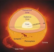
The sun can be approximated as an emitter of blackbody radiation at temperature of 5777K [26]. The long-term average irradiance, that is specific power, from the sun outside the earth’s atmosphere amounts to 1367 W / m2. This value is referred to as the solar constant I0. In fact, I0 is not a constant and the values found in the literature may vary slightly. [27]
Due to the elliptic orbit of the earth, the extraterrestrial irradiance Ion on a surface normal to the sunbeam on day n of the year is
Ion (n) = E0 (n) I0, (1)
With
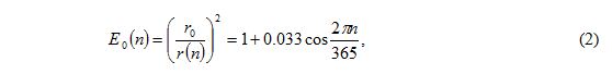
The eccentricity correction factor, raddi r0 and r(n), respectively, are the annual average and the current sun-earth distance at day n. The day member n ranges from 1 on January to 365 December 31. [28]
True Solar Time
The time usually applied in solar-energy calculations is the true solar time T ST. in true solar time, the sun crosses the meridian of the observer at 12:00. The time of day, throughout this work, is given as TST in hours. The conversion from local standard time (LST) into TST reads
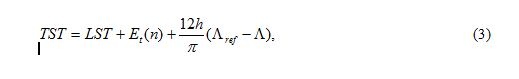
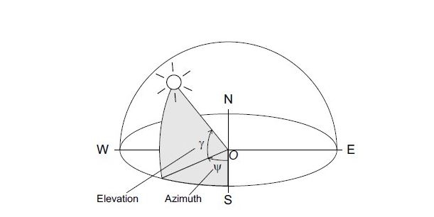
Figure (11): Spherical coordinates of the sun position; observer at the origin O.
With Λ the geographical longitude of a site and Λref the reference longitude for LST, both in radians, positive for western latitude. The added Et is the equation time, which accounts for perturbations in the earth’s rate of rotation. It can be calculated from the superposition of two harmonic functions[28]:

Additionally, there may be one hour correction for daylight saving time.
Sun Position
The sun possition on the celestial sphere is given by the elevation angle γ and the azimuth angle ψ (fig 2).The sun position depends on the date, the time of the day, and the geographical position of the observer[28].
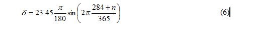
The data at day number n determines the solar declination angle
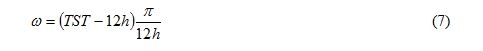
The time of the day is reflected by the hour angle
Elevation γ and azimuth ψ at a certain time and date at longitude Λ and latitude φ are then calculated from
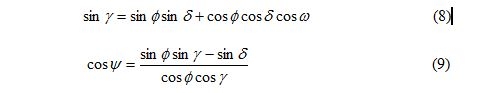
The solar azimuth ψ is negative in the morning and positive in the afternoon. For positions on the northen Hemisphere, it is negative. The declination δ is defined positive during summer on the northen hemisphere. The geographical latitude Φ is positive on the northen hemisphere and negative on the southern.
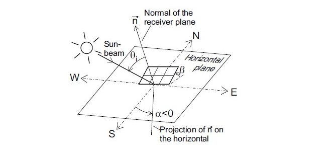
Figure (12): Sun position relative to an arbitarily oriented reciver plane [26].
Arbitary oriented Surfaces
The position of the sun is relative to arbitarily oriented surface is determined by by the angle of incidence θi of the sunbeams (Fig 3). For horizontal surface, the angle of incidence equals the solar zenith angle θz with
![]()
For an inclined surface with tilt angle β and azimuth α, the angle of inclidence ios calculated from
![]()
Where the azimuth angle α runs from the east to west and is zero for the southern orientation. The extra terrestrial irradiance received by an arbitary oriented surface then is
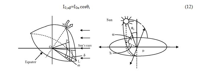
Figure (13): (a)Basic Sun Earth Angle; (b)angles to describe the position of the sun in the sky
Terminology
In the related litarature many terms for the description of solar radiation quantities can be found.Throughout this work the terms are described in the bellow.
Irradiation: The term irradience specifies the rate of energy recived by an infinitesimal surface. The unit of irradience is “W / m2”. Irradiation is the energy recived infinitesimal surface. Irradiation is the time integral of irradition over a specified period. Its unit is “W /m2”.
Beam Radiation (Ib): the solar radiation recived from the sun without being scattered by the atmosphere in called beam radiation. It is direct solar radiation.
Diiffuse Radiation (Id): Solar radition whose direction has been changed through scattering by the atmosphere is known as diffuse radition.
Global Radiation or Terrestrial/ Total solar radiation (Ih): The sum of beam and diffuse radition in hourly on a surface is called global or total solar radition, i.e. Ih = Ib + Id
Solar Geometry / Earth Angle: Earth angle and its components are described in the following ways:
I. Latitude (): The latitude is the angular distance of the point on the earth measured north or south of the equator is latitude. -900≤≤900
II. Longitude: Angular distance measured east and west of prime meridian is longitude
- III. Declination Angle (): Angle made by the joining the center of the sun and the earth with its projection on the equatorial plane, north positive is declination angle. It is zero at the autumnal and vernal equinoxes is 230450 at the summer solstice on june 21 & -23.450 at the winter solstice on December 21 in the northern hemisphere. The range of declination angle is given by -23.450≤≤ 23.150.
- IV. Hour Angle (ω): Angular displacement of the sun east or west of local meridian due to rotation of the earth on its axis at 150 per hour is hour angle. It express the time of the day with respwct to the solar noon. It can be expressed by ω = 15(t-12)
Angles to Describe the position of sun in the Sky:
Sky: Figure (b) represents the angles to describe the position of the sun in the sky. Angles are described the position of the sun in the sky. Angles are described in the following ways:
I. Solar altitude Angle(αS): It is the angle between the projection of the sun’s rays on the horizontal plane and the direction of sun’s rays.
II. Zenith Angle(θZ): It is the angle between the sky’s rays and a line perpendicular to the plane through the point. Here, θZ + αS = π/2.
III. Solar Azimuth Angle (γS): It is the angular displacement from the south of the projection of beam radiation on the horizontal plane
The term radiation is used soley as a qualitative term in order to describe the physical phenon.
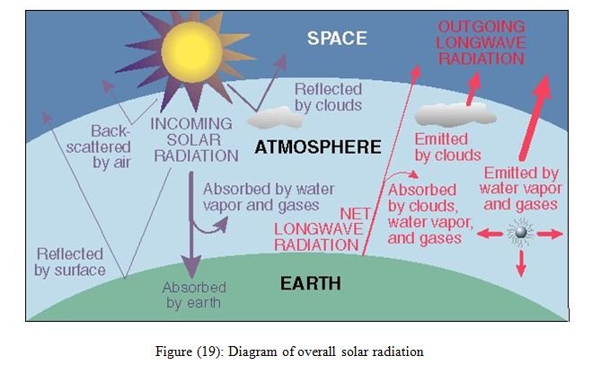
Terrestrial Radiation
While passing the earth atmosphere, the sunlight is attenuated. Some of the sunlight is absorbed by air molecules, water vapour and dust. Some is scattered, either back
Into space or forward to the earth surface, by ozone, water and CO2. Some of the light passes the atmosphere unaffected and is either absorbed or reflected on the ground [28].
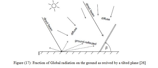
The radiation arriving on the ground directly in line from the sun is called direct or beam radiation I. The scattered radiation is called diffuse radiation D. the radiatipon reflected by the ground, is ground reflected radition R. the sum of the three component is called global radiation G[29]:
![]()
Where the subscript indicate azimuth and tilt angle of the reciver plane. If α and β are no specified, the surface is suppose to be horizontal. The ground-reflected radiation R on a horizontal surface is always zero by rule.
Cloudless Skies:
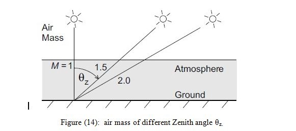
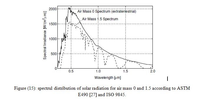
The attenution of sunlight within the atmosphere is selective with regard to wave length. Therefore, the spectrum of sunlight at the earth surface depends on the optical path length of the sunlight through the atmosphere.The relative optical path length inside the atmosphere is called air mass M. it can be approximated as
(14)
When the sun is situted in the zenith above the observer, the air mass is one. Outside the atmosphere it is zero. In modarate latitudes, often M=1.5 is assumed as a characteristic value figure(13).
The air mass, defined in (14), is a purely geomatric quantity. With regard to the defination of solar reference spectra, the air mass is moreover applied as a characteristic indicator for the spectral distribution. [30]
Figure 5 shows the extra terrestrial spectrum and and air mass 1.5 spectrum from a cloudless sky on a 37 degree tilted plane according to ASTM E490 [27] and ISO 9845 respectively, The selective attenution for different wave lengths is well visible.Under a cloudless sky, the solar irradiance on the earth surface at a given time and dateonly depends on the atmospheric turbidity. Turbidity here describe the scattering of solar radiation by mater other than dry air molicules. Under a cloudy sky, the solar radiance on the earth surface is additionaly affected by passing clouds. The attinution of the solar radition in that case happens to be at random.
Cloudy Skies
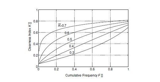
Solar radiation under cloudy skies was first investigated on a statistical basis by Whillier[31]. He drew cumulative frequency distributions of hourly irradiation for differeant geographical positions, seasons and hours of the day. Shortly later, the clearness index K was introduced by \liu and Jordan [32] as a parameter that accounts for the stochastic atmospheric conditions at a given site. It is defined as the ratio of terrestrial to extraterrestrial irradiation:

Where the bar denotes time integrals of global and extrateresterial irradiance oner usually one hour up to the month. For horizontal surface the subscripts α and β are omitted.
According to Liu and and Jordan [32], the cumulative probability of the daily clearness index K during one month can be described analytically by Boltzman distributions, which are fully determined by the monthly mean clearness index K. Lius and Jordans findings were generalized when it was found that their expression could be extended to any given set of daily clearness-indes values[33]. For any specified mean values K . the probability distribution of daily clearness index K can be described by the curves in figure6, independently of any geographical or sesonal influence.
The instantaneous clearness index k may be defined in an analogus way based on global andextraterrestrial irradiance. His is done for the analogus of solar Irradiance fluctuations in [34]. There, the stochastic properties of the instantaneous clearness index and discussed in depth based on emperical data
Available Radiation:
The global irradiance on the earth surface usually takes values upto 1200W / m2 on a plane perpendicular to the sunbeam. If turbidity is low, this value can be measured even at instants with a very high Air mass.In some case also values higher than I0n can be observed. The originate from reflection at the edge of clouds leading to a local increase of the solar irradiance on the ground [35].

Figure (16): Generalized cumulative probability distributions of the daily clearness index K with parameter K [33].
When the sun is coverd by passing clouds, the direct radiation is blocked and the irradiance often drop’s down to values around 200 to 300 W / m2 anmd lower. On a day with scattered clouds as it is typical for the Belgium modarate meritime climate, a high number of such transition may occcur.
On an annual base, the global irradiation in belgium is in Belgium is about 1000 kWh/ m2 , of which more than 55% is duffuse[36]. In southern Europe the annual global irradiation from 1300 to 1800 kWh/m2. In some of the worlds tropical deserts up to 2400kWh / m2. In some of the worlds tropical desert up to 2400 kWh / m2 may be reached.
Conversion to Arbitrarily Oriented Surface:
Global and often also diffuse radiation on the horizontal plane is measured worldwide at many different sites, mostly as hourly averages of irradiance. A number of models have been developed for the conversion of horizontal irradiance data into irradiance on an arbitrarily oriented surface.
Direct Radiation:
The conversion of direct radiation is a mere matter of trigonometry. The dirrect irradiance on the horizontal plane is the difference between global and diffuse irradiance. It is converted for a plane with azimuth α and tilt angle β according to
With γ and θi according to (31)-(16) for each instant time.
Ground reflected Raditation:
The ground reflected raditation depends on the structure and reflectance on the ground. For practical purpose, it mostly as assumed to be isotropic. For surface with directional reflectivity (like windows or a water surface) this is not true. However, the error is significant in only a few cases. With regard to solar radiation, yhe reflectance to the ground is termed albedoρ. The ground-reflected radition Rαβ on a titled surface follows from the multiplication of the global radiation by the albedo of the ground and a view factor 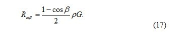
The view factor (1-cosβ) / 2 accounts for the geomatric relationship between the tilted reciver surface and the emitter surface, in this case the surrounding ground [26].In practice, often an albedo of ρ=0.2 is applied [26], which is a typical value for dry base soil. For highly reflective surface as, for example, snow, the albedo title plane when title angle is high. At loe tilt angles, the albedo has a minimal effect due to the low view factor.
Diffuse Radiation:
Assumeing the diffuse radiation with its intensity uniformly distributed over the sky dome, it may be treated similar to the ground reflected radition. The respective isotropic model has been developed by Liu and Jordan [103]. The diffuse irradiance on a tilted surface is
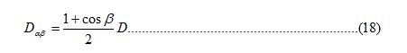
Where (1+cosβ) / 2 is the view factor for the geomartric relationship between the tilted receiver surface and the sky dome.
The isotropic model is resonably accurate for cloudy skies. However, under scattered clouds and clear skies, it underestimates the diffuse radiation on surface tilted towards the equator. Under clear skies, the diffuse irradiance is articulately anisotropic. The radiance, that is, irradiance per space angle of the sky dome, exhibits local maxima both around the solar disj and close to the horizon.
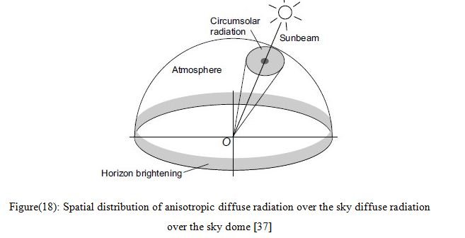
The fraction of diffuse radiation orginating from srround the solar disk is called circumsolar radiation . The increase in radiation in a band close to the horizon is reffered to as horizon brightenibg (Figure17) .
A circumsolar model has been introduced by Hay and Davies. Here, the circumsolar radition can be taken into account by parameterzing Dαβ an the sum of an anisotropic and isotropic fraction:
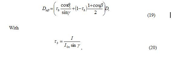
The atmospheric transmission factor for beam irradiance.
The most precise anistropic model up to now has been intriduced by Perez [37].Circumaolar radiation is consideed inside a circle of variable size arround the sun.Horizon brightning is considered inside a horizontal band of variable height at the horizon. The diffuse irradiance on a tilted plane according to pezer’s model amounts to
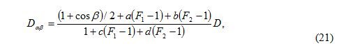
(21)
Where a and b are view factors of the circumsolar circle and the horizon band, respectively, with regard to the reciver plane. The parameters c and d are view factors of the circumsolar circle and the horizon band, respectively, with regard to the horizontal plane. For a given circumsolar circle and horizon band, a and b depends on the angle of incidence θi, c depends on the solar zenith θz and d is constant. The parameter F1 and F2 describe the enhancement of radiation inside the circumsolar circle and in the horizon band, respectively. They vary independently with the radiance distribution[38].
There is a large varity of F1 – F2 pairs depending on zenith angle and sky conditions. Parameters for the anisotropic distribution of solar radiation over the sky dome have have been elaborated in [37]. The subject is not further discussed at this place based on[37], the application of the perez model should pose no further difficulty.
Direct, ground-reflected, and diffuse irradiance on an arbitrarily oriented surface can be calculated by means of one of the approches presented. The global Irradiance on a plane with azimuth α and tilt angle β is the some of the three fraction according to [38].
The different available conversion models for diffuse irradiance on inclined surface have been compared by IEA (international Energy Agency)’s solar heating and cooling programme (IEA SHC). The authors found the highest accuricy for the perez module. However, the module of Hay and Davies is only slightly less precise. As a consequence, the model of Hay and Davies is still frequently applid, especially when only a limited database is avaible for the determination of F1 and F2.
Radiation Measurement:
Global solar radiation is generally measured by pyranometers, For measurement regarding PV applications, usually either a thermal pyranometer (figure 15) or a solar cell radiation sensor is applied (figure 16).
Thermal Pyranometers:
A thermal pyranometer measures solar irradiance via the temperature of a black absorber by means of a thermocouple. Thermal pyranometers have a constant spectral response over the entire solar spectrum. The absorber is usually covered by a hemispherical glass done ensuring independence of the angle of incidence[38].
According to ISO 9060, pyranometers are classified according to their precision into “second class”, “first class” and “secondary standard” [40]. Secondary-standardpyranometers are the most precise. For a secondary-standard instrument the maximum error of hourly irradition is 3% [41]. Due to their thermal intertia, pyranometers feature no immediate response to variations in solar irradiance. The thermal time constant of a secondary-standard pyranometer is approximately τ = 4s. For a first-class or second-class device, the time constant is much longer [42].
In order to measure diffuse irradiance. Thermal pyranometers can be equipped with a shadow ring. The shadow ring blocks direct radiation and the pyranometer recives only diffuse radiation. The position of the shadoe ring must be addapted every couple of days accourding to the variable solar declination throughout the year. This can happen manually or by means of small motor drive.
Referense Solar Cells:
Solar cell based radiation sensor measure the solar irradiance via the short circuit current of a solar reference cell. As an approximation, the short circuit current is proportional to the solar irradiance. However, the precise measurements, the result must be compensated for the effect of cell temperature on the short circuit current. The cell temperature is either derived from the open circuit voltage of a second identical reference cell or it is messured directly at the back of the refference cell or it is messuired directly at the back of the reference cell by means of a resistance thermometer.
Unlike the thermal pyranometers, solar cell radiation sensors applied to PV monitoring mostly have not a hemispherical but a flat glass cover. The spectral response reference-cell radiation sensors depemds on the applied solar cell material. On the one hand, the flat glass cover leads to increased reflection with hogh angles of irradiance.
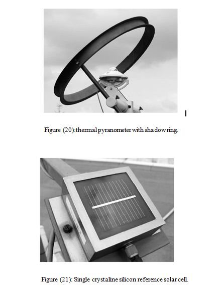
Figure (21): Single crystaline silicon reference solar cell.
On the other hand, crystaline sillicon reference cells tend to overestimate the solar irradiance at low solar elevation angles due to the relatively increased red content of the spectrum with high air mass. The silicon cell is more sensitive in the red than in the blue range of the visible spectrum[30].
Regarding reflection losses and spectral response, reference cells behave exactly as PV modules made of the same material. This is why reference cell behave exactly as PV modules made of the same material. This is why reference cells are mainly applied for the measuring the irradiance on the PV array plane. If the reference cells has been properly chosen, the measured irradiance considers reflection losses and deviations from the AM-1.5 spectrum of the applied PV modules[42]. The effect of thermal inertia on the measurement of a solar reference cells is negliable.
Altough the prices for reference cells vary greatly depending on their precision and robustness, they are still notably cheaper than a secondary-standard pyranometer. This and the higher thermal inertia of a thermal pyranometers is mainly limited to high-precision measurements of global and diffuse radiation on the horizontal plane according to meterological standards. In-phase irradiance values for the energetic evalution of PV systems are usually measured by a reference cell.
Estimation of Tilted surface radiation:
Flat-plate solar collectors absorb both beam and diffuse radiation components of solar radiation. To use horizontal total radiant ion data to estimate radiation on the tilted surface plane of a collector of fixed orientation, it is necessary to know R, the ratio of total radiation on a tilted surf ace to that on the horizontal surface. The amount of solar radiation falling on a tilted surface is the sum of the beam and diffuses radiations falling directly on the surface and the radiation reflected on the surface from the surroundings. If one knows the tilt factor for a specific tilt angle for a location then he can easily estimate what will be the radiate ion on the tilted surface for Solar Home System. The ratio of the beam radiation falling on a tilted surface to that falling on a horizontal surface is called the tilt factor (Rb) for beam radiation. For the case of a tilted surface facing south in the northern hemisphere, Rb and is given by
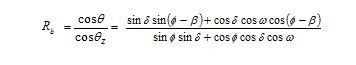
Where, θ is the angle between the beam radiations on a surface and normal to that surface, θz zenith angle, is the latitude, β is the tilt angle, δ is the declination for the average day of each month, w is the hour angle for the tilted surface for the average day of the month. The tilt factor Rd for diffuse radiation is the ratio of the diffuse radiation falling on the tilted surf ace to that falling on a horizontal surface. The value of the tilt factor depends upon the distribution of diffuse radiation over the sky and on the port ion of the sky dome seen by the tilted surf ace. Assuming that the sky is an isotropic source of diffuse radiation, we have
Assuming that the reflection of the beam and diffuse radiations falling on the ground is diffuse and isotropic and that the reflectivity is ρ, the tilt factor for reflected radiation is given by
where ρ is the surface albedo. The monthly surface albedo values are employed from
NASA and these lie between 0.12 and 0.16.
Thus the hourly tilt factor, R can be given by
R= HT/H = (1 – Hd / H)Rb + (Hd/H)Rd + Rr
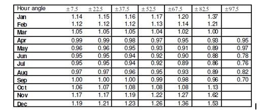
Table: Hourly Tilt factor s for Latitude tilted south facing surface at Dhaka
Tilt angles should be chosen so that the solar devices can get significant available solar radiation. In summer the sun’s path is short and it shines almost on the zenith at noon. But in winter the sun path is long and it has a path closer to horizontal at noon. Hence if we keep the solar device horizontal in summer it will get more sunlight at noon and if we keep the device tilted in winter from the horizon it will get more sunlight. One can also track the sun both in the sun’s direct ion of path and the time of the day. In Bangladesh a study shows that if one simply changes the tilt angle at 400 for winter (October-February) and 100 for summer (March-September) then he can achieve higher tilt factors.
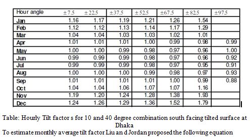
Figure (22): Monthly tilt factor for Dhaka
To find the tilted surface radiation one has to multiply GHI data by tilt factor. From the above figure 21 it is clear that the total radiation will decrease if one keeps the surface at latitude tilt angle in summer season at Dhaka. To get higher values from the solar system one may practice to tilt the surface, two times over the year as above tilt angles. [43]
In Bangladesh the sunlight falls directly in summer and it falls transversely in winter. So, it is desirable to put the panel at 45 degree slanting in summer and 15-20 degree in winter to get the best result. But it is troublesome to put the panel at different angles with the change of seasons. The experts arrived at a decision to place the panel at certain angle taking the average angle of the sunlight throughout the year that is from January to December to avoid placement of panel at different angles at different times to get more electricity. This angle is 23 degree to south. Care should be taken so that the shade does not fall on the panel. Shade or barriers of sunlight cause less efficiency of the panel. [44]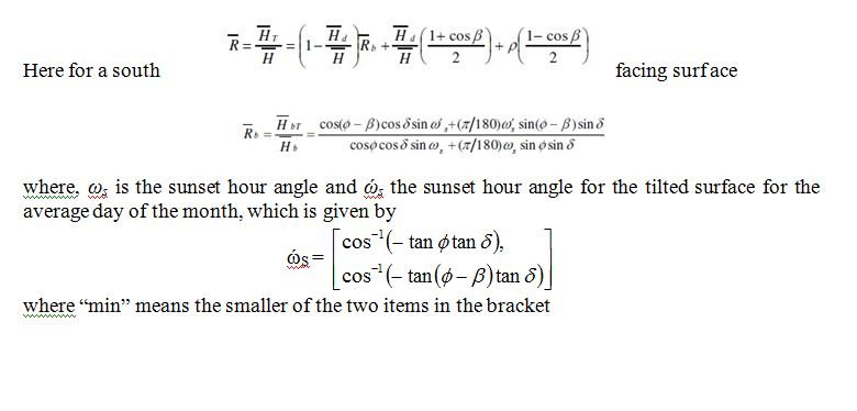